Whilst I’ve been pretty busy lately, I recently made another order from Mindkits and got to work with testing some of my ideas for my Arduino-based remote management solution for my home server.
There’s 4 major parts to this solution
- Connectivity to the computer’s serial port (a motherboard 10-pin header) and being able to communicate with the serial port using the Arduino.
- An Arduino controlled switch to turn the computer motherboard’s reset pins on and off.
- Connection into one of my old HTC Magic Android cellphones.
- Connection of 1-wire temperature sensors in key parts of the server’s case.
I’m using a stock standard Arduino Uno/Eleven for this project, for two main reasons:
- The HTC Magic phone is quite an old model of Android phones, effectively it’s the second generation after the original G1 and was the first officially available Android phone in New Zealand. Whilst I have loaded the last stable version of Cynogenmod released for it onto the phone, it’s only Android 2.2 and doesn’t feature the Android USB Accessory API support, so there was no point getting something like the USBDroid model.
- Rather than paying extra for ethernet connectivity, I’m planning to write an Android application that runs on the phone in the background that provides all the logic behind the remote management program for the server and connectivity via Wifi, 3G and SMS – I figure that the Android platform is better places for the management program anyway with a more sophisticated software
I purchased some protoshields for the Arduino, so my plan is to develop all my circuit logic as an addon shield so it will be possible to stack other shields on in future if I want to add some new applications/functionality to the system.
I’m new to the electronics, the Arduino coding AND the Android development requirements, so it’s an awesome learning curve project for me to start getting my head around all these technologies. :-)
The easiest bit to solve is the control of the computer’s reset header – I need this in order to be able to reboot a crashed system, something that has happened a couple of times due to flaky hardware.
To control the reset, I can use a simple transistor switched circuit, there’s a few resources around for novices to follow, I found this one useful. The only concerns I have is that I need to research and find out what the voltage on the reset headers is – I’m assuming 5V, but it could be anything from 3V to 12V….
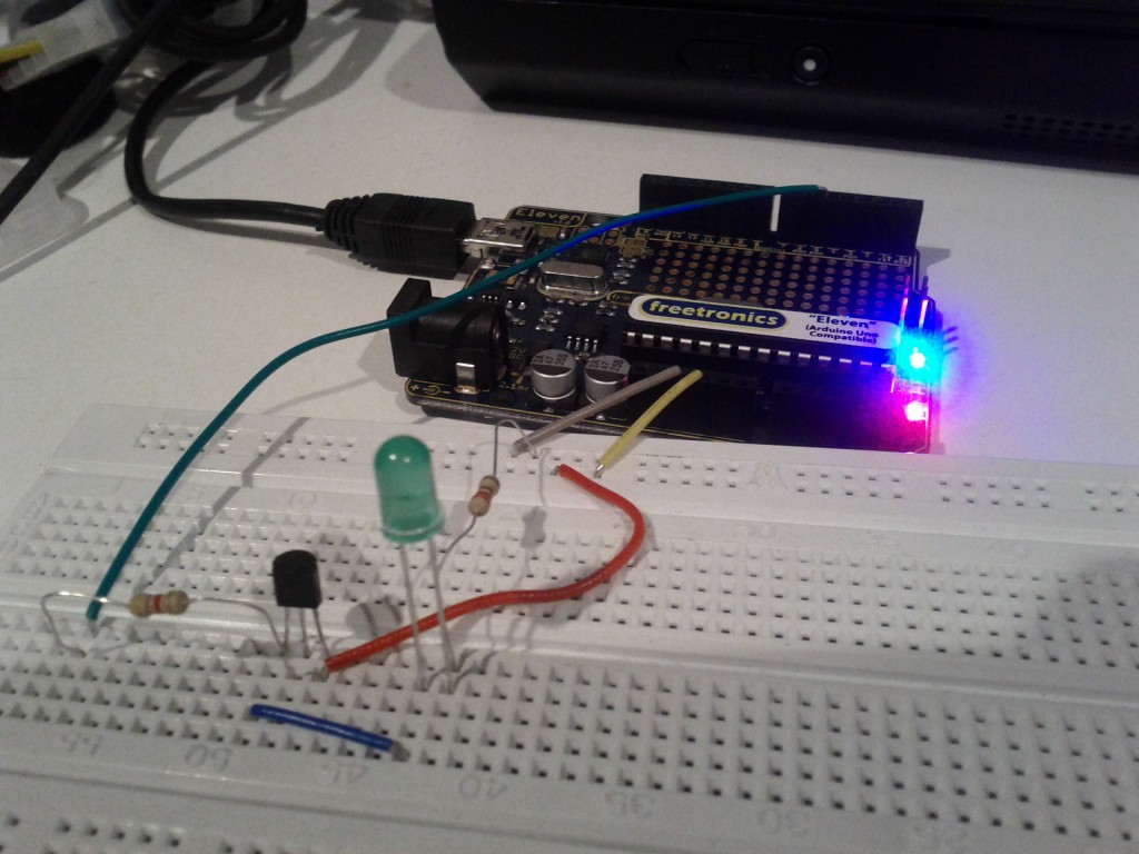
Tested the switch by using the Arduino to turn on the LED using a transistor.
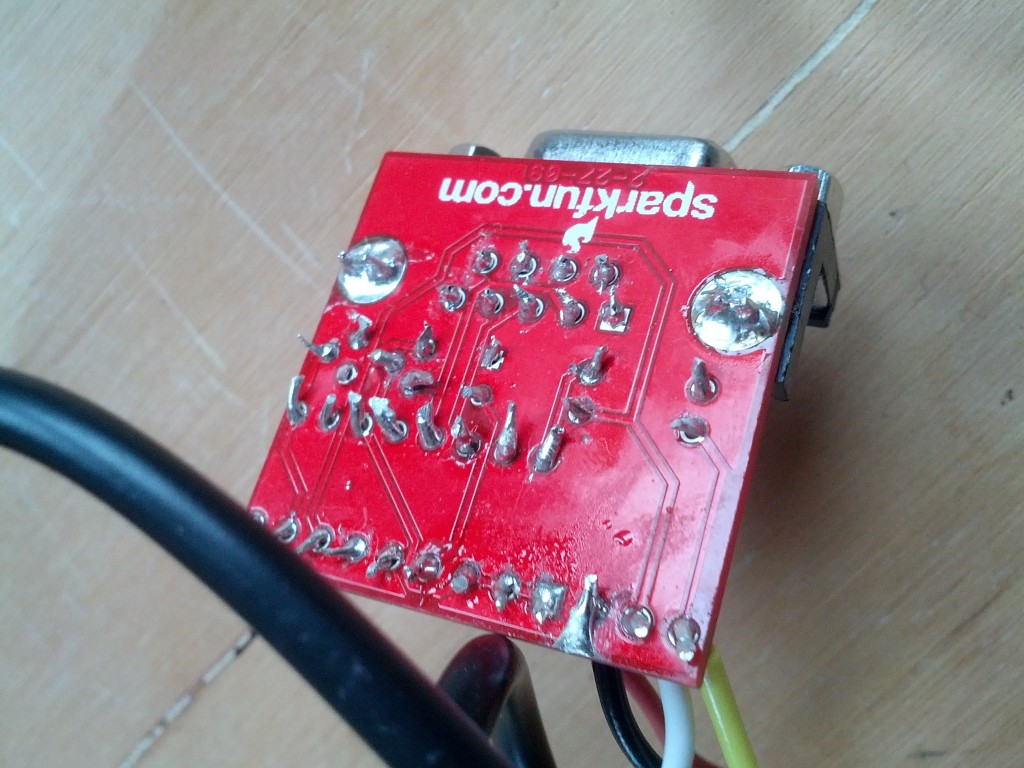
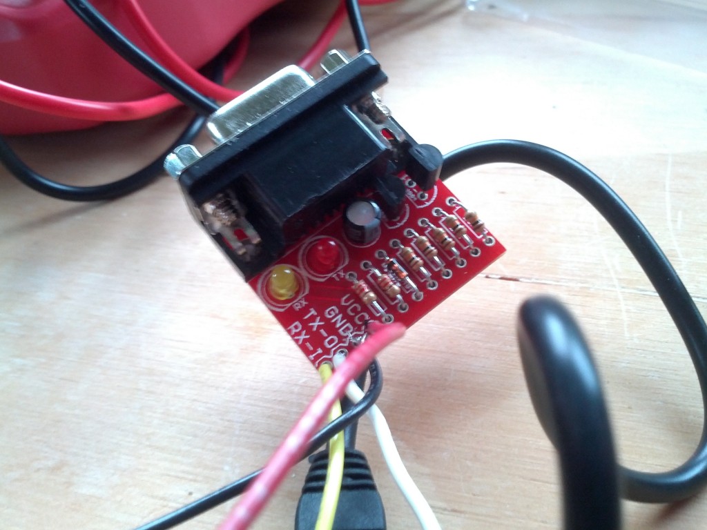
The connectivity to the server seems pretty straightforwards – I’ll be using an RS232 shifter circuit (like this one) to connect the PC serial port to the Arduino, although I might end up re-implementing that circuit directly on the protoshield and using a 10-pin IEC connector to plug directly into the motherboard’s serial header
The phone will be connected using the debug serial port in the HTC Magic – it seems a number of the earlier HTC models can provide serial over some of the extra pins in the ExtUSB plug they use.
I’m not totally sure how I’ll be connecting both serial ports just yet – the Ardunio has one hardware UART onboard on pins 0 and 1, but I’m not sure if I can use those without losing the ability to manage the Arduino via it’s USB port – ideally I want the capability to still update the Arduino from the server it’s connected to.
It is possible to connect additional serial ports using software and there’s even a handy library for it, so I have that option for one or both ports. I’ll just have to code my software to be aware that the connection might be lossy or imperfect and to be patient and retry stuff.
I purchased an (expensive!) breakout board for the ExtUSB port which will make the soldering a *bit* easier, but considering the size of it, it still won’t be any walk in the park…
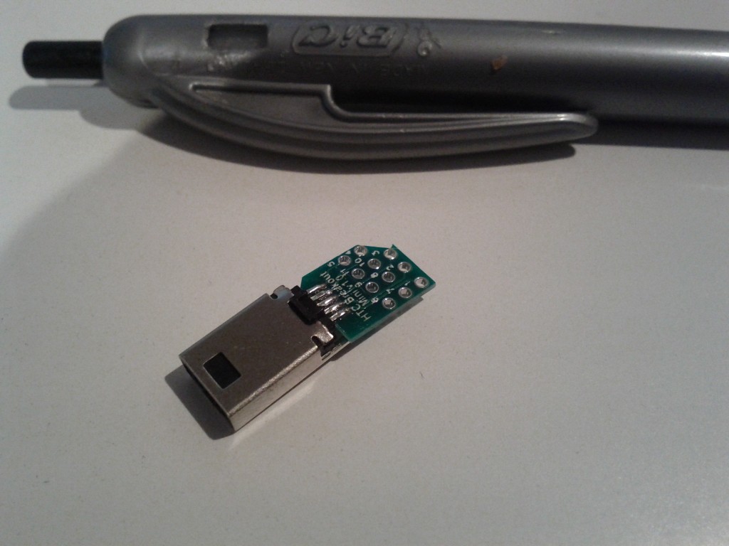
From uber-tiny to just plain tiny :-/
Fortunately since I’m using Cynogenmod, all the OS-side software is sorted and the kernel built with the correct parameters to enable the serial port functionality, providing me with a /dev/ttyMSM2 character device out-of-the-box.
Because I wanted to give it a go and see how the phone ran, I used some header pins to connect to the breakout board as they fit in the holes snugly – there must be some better tools available for connecting to PCBs and device legs without soldering for testing purposes, so I’ll need to do some more research for future.
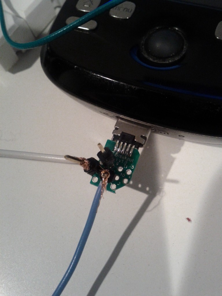
World’s dodgiest serial connection – also GND and TX pins connected only, it sends 2.8V into the Arduino which is OK, but I need to do a step down circuit before I can transmit from 5V back into the phone.
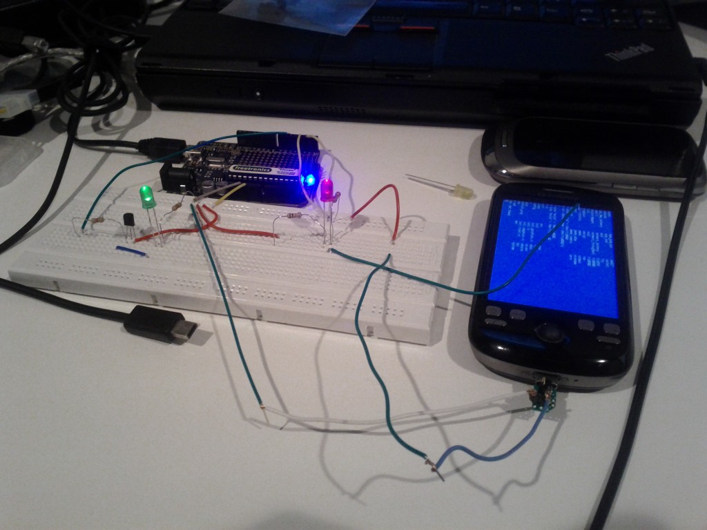
Hacky hacks
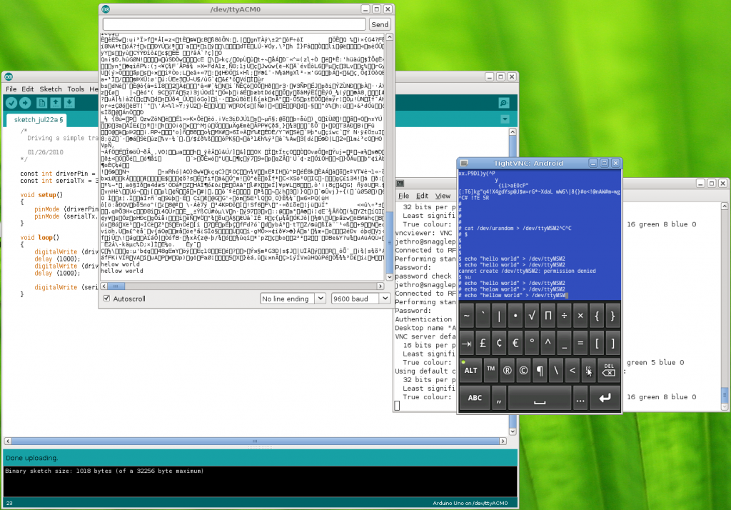
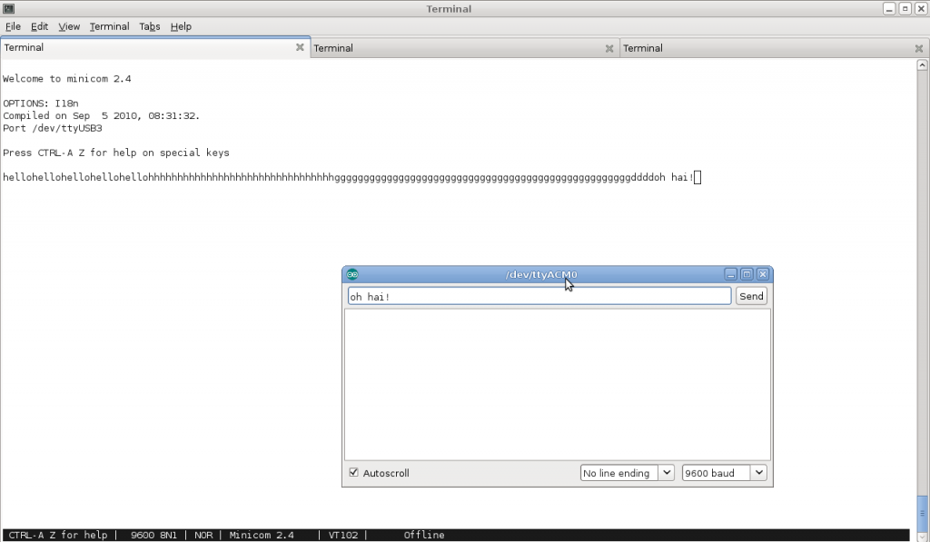
VNCd into the phone and sending messages over the serial line, which is connected to pin 1 (TX) on the Arduino, so the messages appear in the serial monitor
Based on these results it’s looking good – at least I’ve validated my understand of what is possible, so the next step is to turn some of this into a proper circuit.
My current plan is to do a short wire run from the ExtUSB connector breakout board into a small PCB which will split the output into the 3 wires for serial (RX, TX, Ground) and also take the 4 wires for USB and connect them to a USB port, so that I can plugin a USB cable to charge and manage the phone. From there, I can run the 3 serial wires to a header on the protoshield I’m building to connect into the Arduino.
I’ll have to work out how the Android phone and the Arduino will communicate for the management functionality, at this stage I’m planning to have an app that would send specific commands to the Arduino via serial and maybe the ability to get the output from the server’s serial port via the serial link to the Android phone by encapsulating the data or some other behavior.
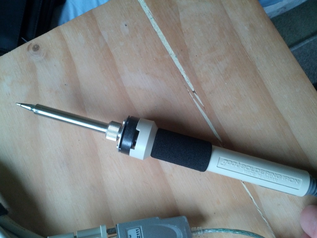
Next steps is to get a better soldering iron so hopefully will be able to do the initial soldering I need for the HTC magic serial connection next weekend. :-)
