Tag Archives: home sweet home

2020-2022 mega update

It seems somewhere along the way I’ve lost my passion/time for updating this blog. I personally blame getting the bike as now I have yet another exciting way to spend rather limited amounts of available time, but it’s probably largely thanks to the massive renovations we undertook in 2020-2021 which has such sucked up any spare time.

When we brought our house in 2014, the roof had been flagged as a likely problem and due a replacement. Naturally we had zero money after buying the house, so managed to bodge the roof along for a few more years with some improper use of silicone sealants and managed to squeeze out another 6 years of life, but in 2019 it got to the stage where it was clear it wasn’t going to be possible to bodge any more and would need the long overdue full replacement as we were starting to experience leaks that could no longer be patched around.

‘ol leaky

So we bit the bullet in late 2020 and kicked off a replacement. Given we’d need scaffolding for this project, we decided we’d roll it into part of a wider renovation/upgrade project and do some other big ticket items on the house at the same time and wrap it into a small loan extension on the current mortgage whilst rates were sub 2.5%.

Before the roofing work started, we made the choice to remove the natural gas connection from the house. Ripping it out had multiple benefits:

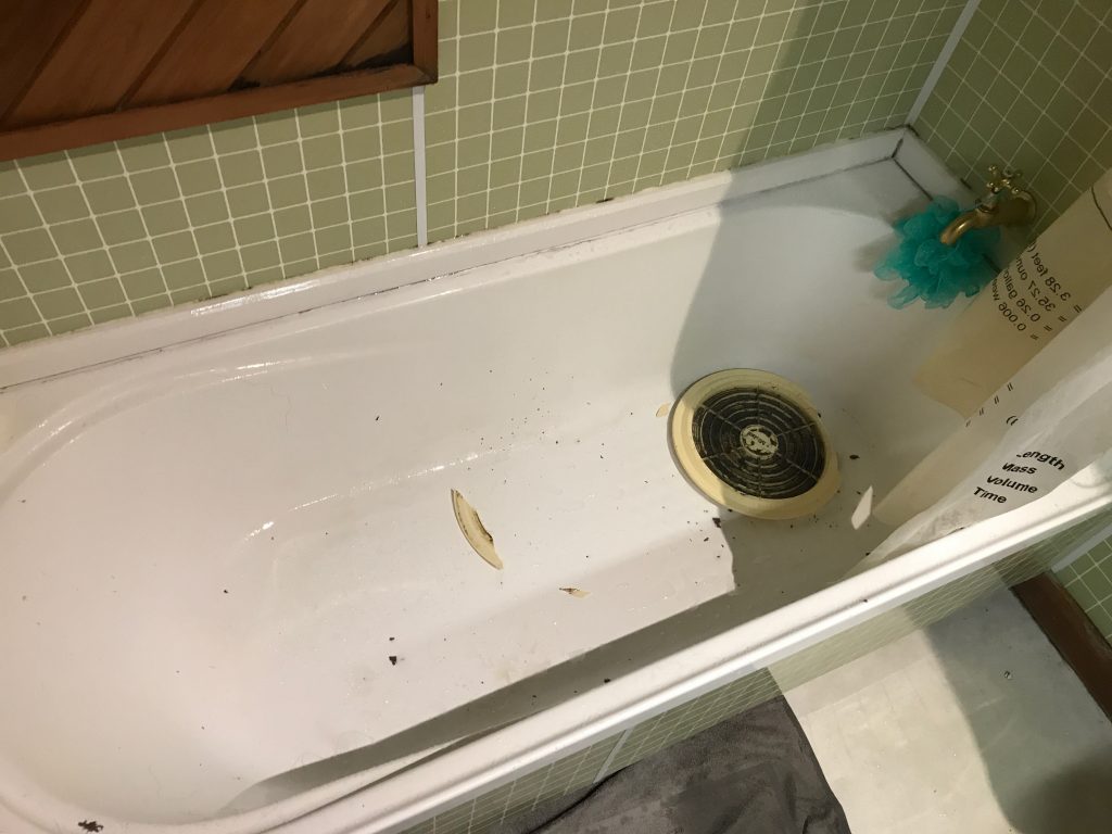
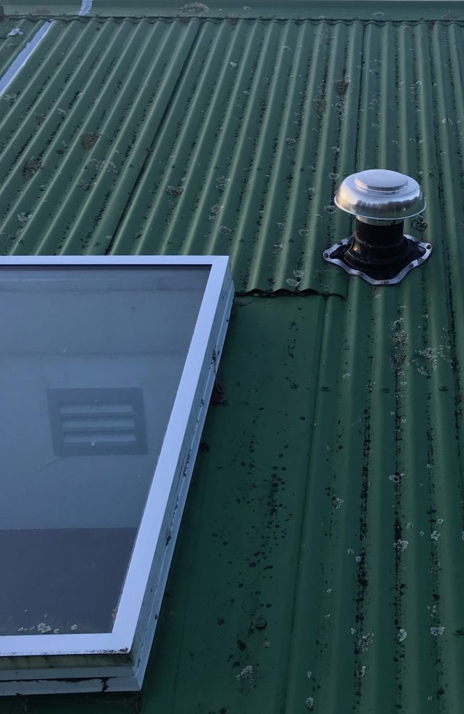
  1. Firstly we needed to remove it before the new roof went on as the old gas cylinder hot water had a flu that went up and through the roof, and we didn’t want to cut a hole in the new roof for an old system that was due replacement. So it needed to come out as the first step.
  2. Secondly all our gas appliances dated back to the 90s and all were end of life with various quirks and features. We had an old unflued gas heater that we’d never used for health reasons, the old hot water cylinder and very fickle part broken gas stovetop.
  3. Finally for added incentive, the gas lines company were starting to be jerks and pressuring us to move the gas meter on the street due to new health and safety rules preventing them from checking the meter where they had originally installed it. There was some disagreement between them and us about who’s problem that was, but we were looking at many thousands of potential costs to rectify if we lost that argument.

We had no love for gas for cooking, it’s expensive to keep with line charges and is also a fossil fuel and having pipes full of explody gas in an earthquake zone has never filled us with confidence. So we were more than happy to rip it out and replace.

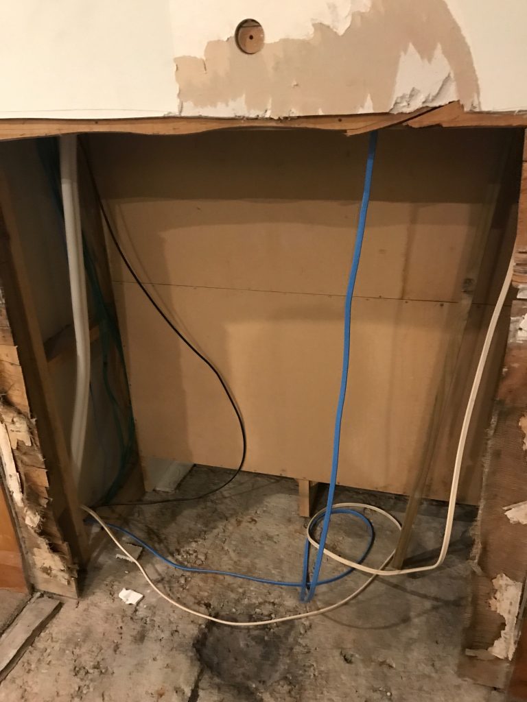
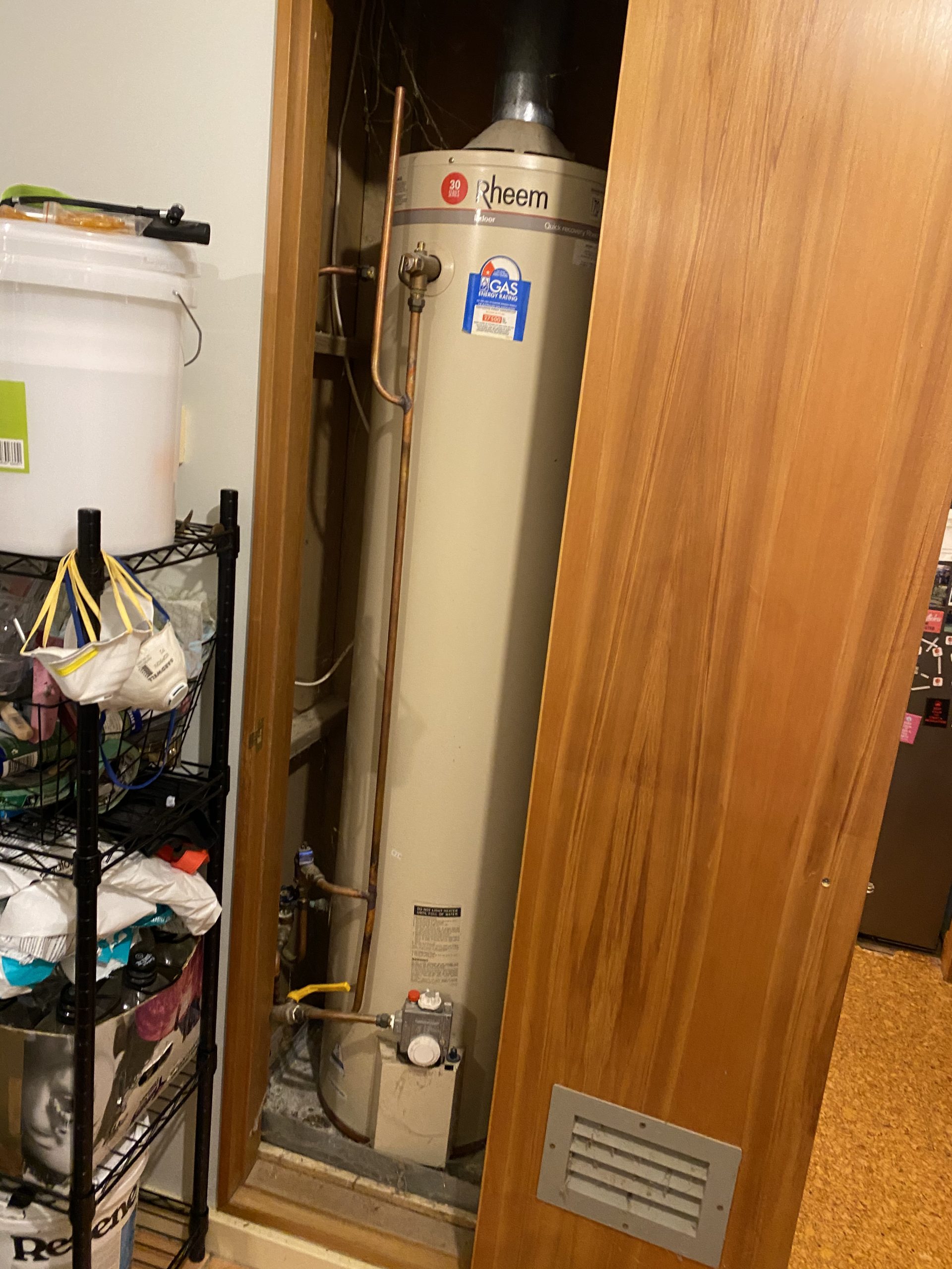
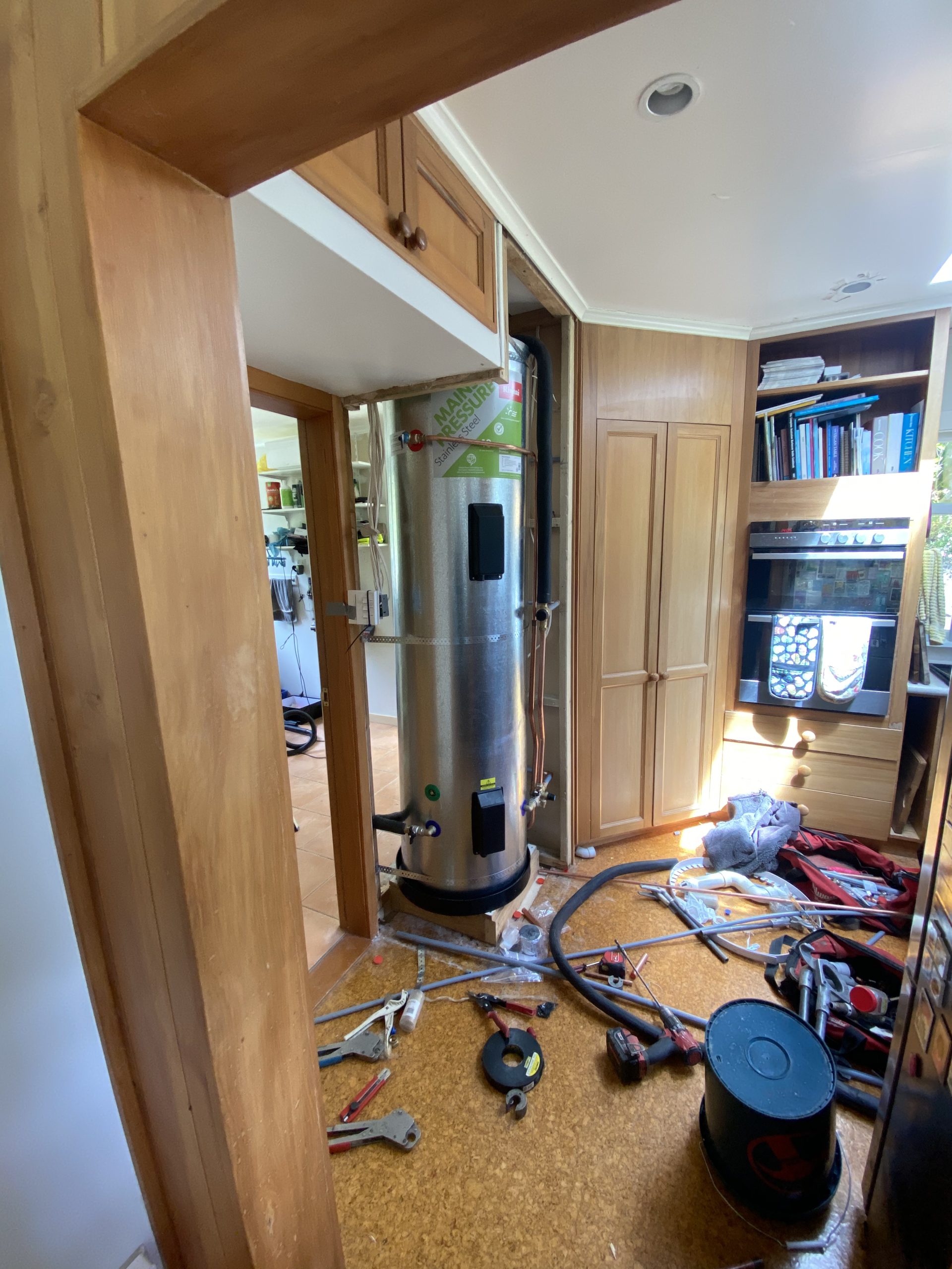
The first big challenge was that our old 170l gas cylinder was located inside the house. The hotwater cylinder installer really really wanted to install the new one on the outside of the house which would be very easy, but IMHO would have looked visually terrible given the layout of our property and not really having a hidden utility space where something big and ugly like that could be located.

To fix this, I ended up demolishing the entire cupboard that existed around the old hot water cylinder, providing a space for the new cylinder to go in and then rebuilding a new cupboard around the installed cylinder.

Old 1-star efficiency gas cylinder
300l electric cylinder going in after demolishing the old cupboard

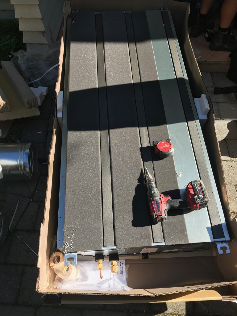
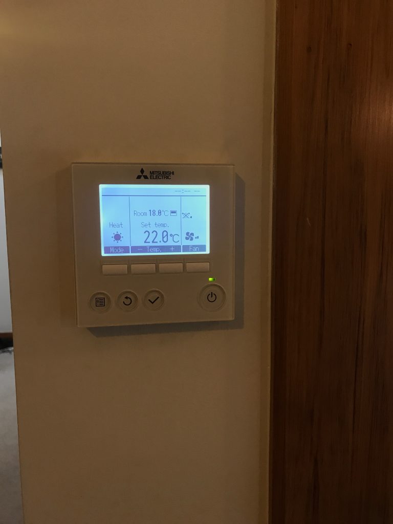
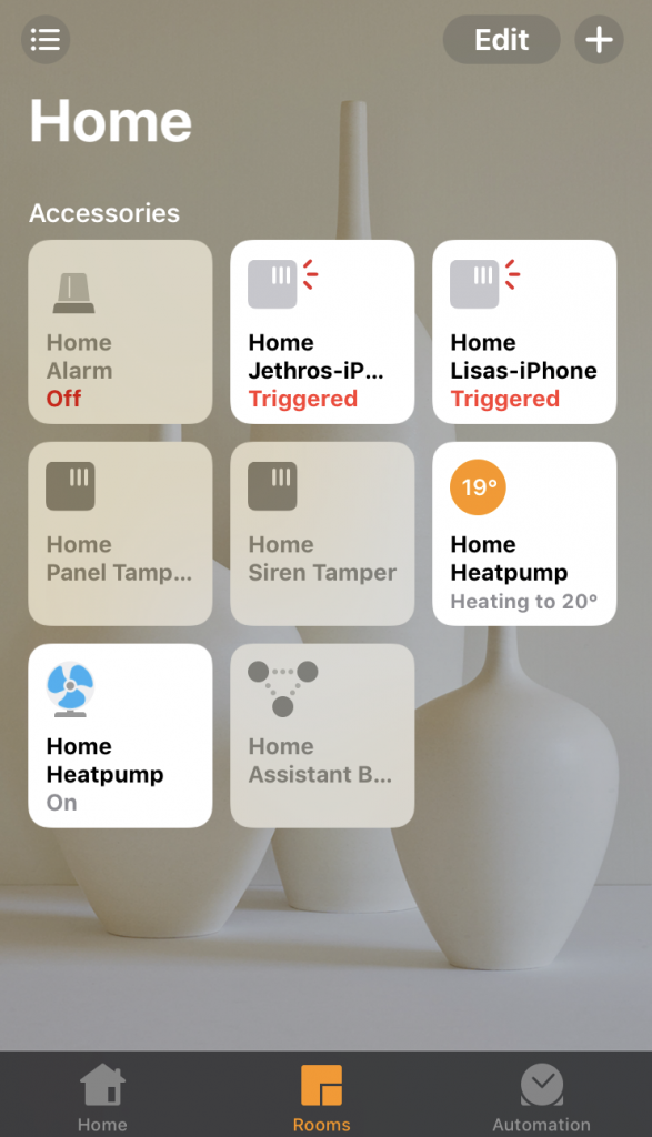
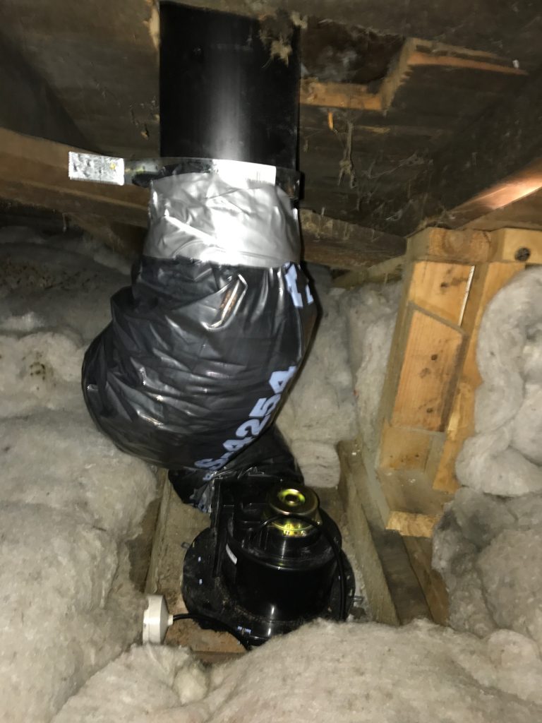
An electrical cylinder can never get more than 100% of theoretical efficiency using electrical resistive heating. So given my love for heat pumps, we paired this new cylinder with a heat pump hot water system to give us a lower running cost solution with potential efficiencies around 300%.

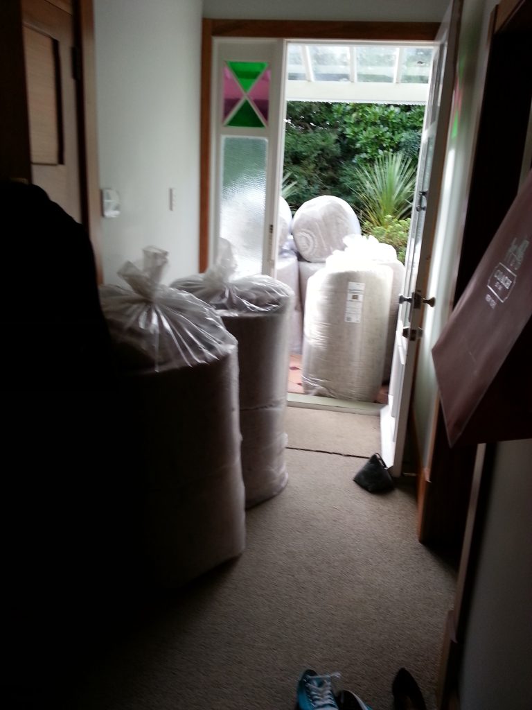
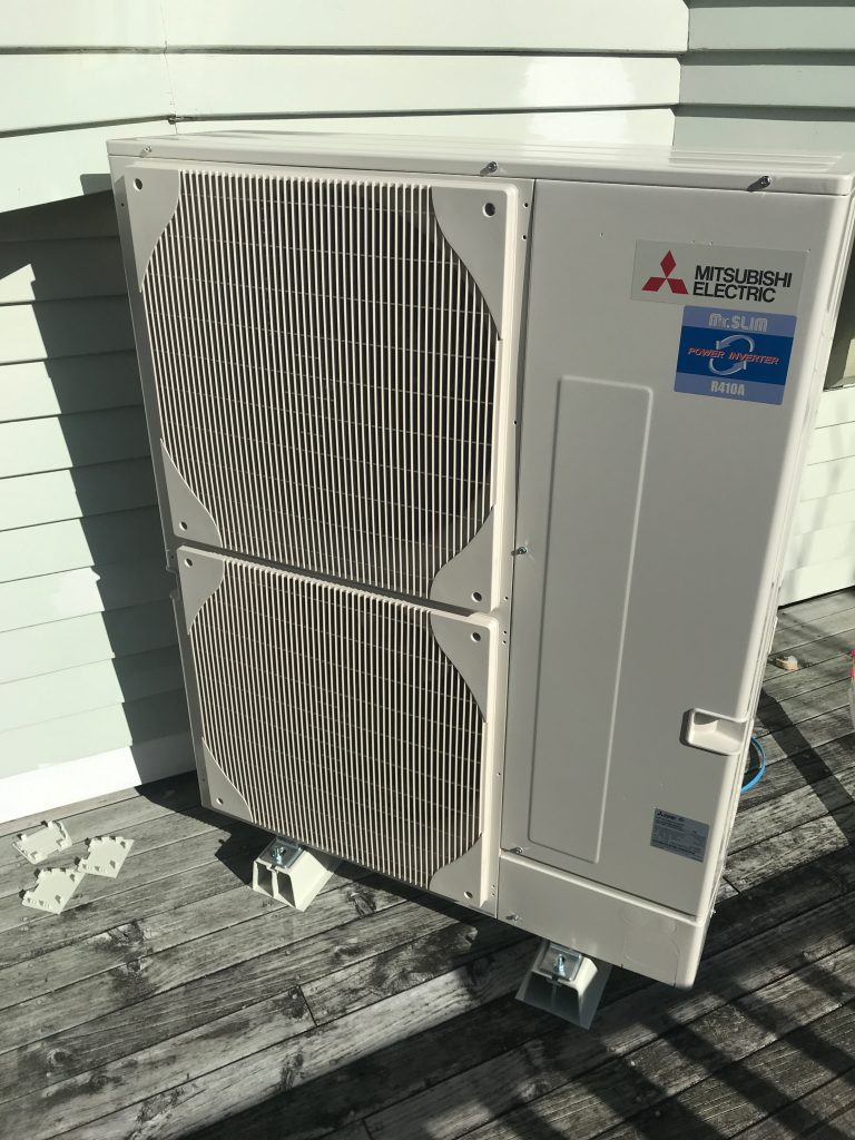
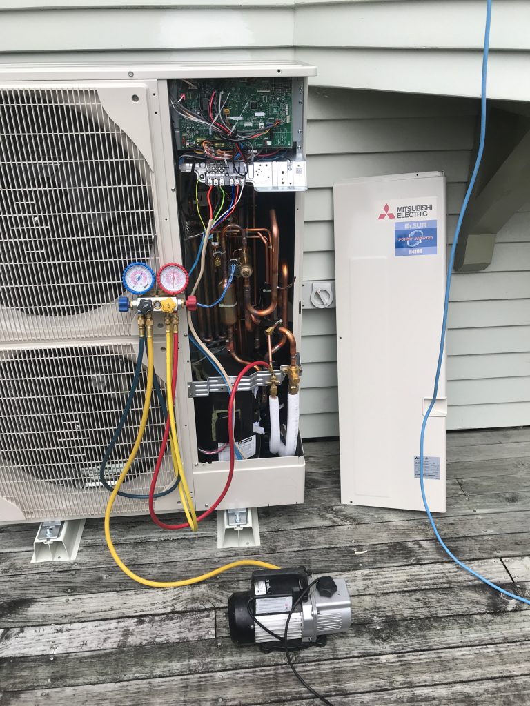
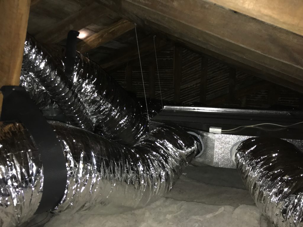
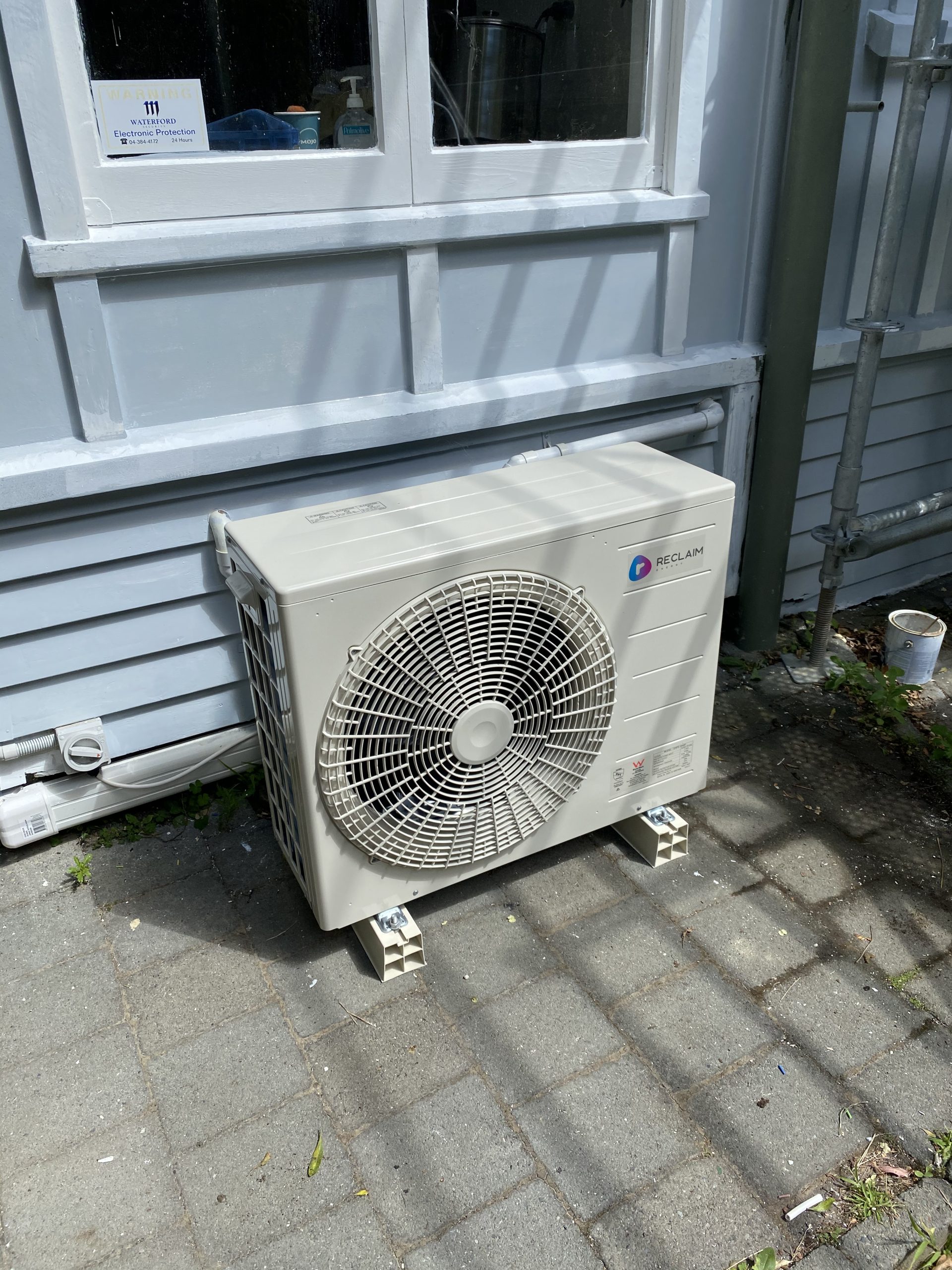
Essentially there’s a small outdoor heat pump unit (like you would have with a typical mini-split system). This pulls heat in from the environment and turns it into hot water. Unfortunately the technology still requires a sizeable cylinder to act as a reservoir hence why we still have a standard 300l cylinder inside, but I hope that at some point they evolve the technology to the point where it can run tankless and be a drop-in replacement for an instantaneous gas boiler.

We looked at some different brands/options. Some brands required their own special cylinders, this seemed to be the models which pumped refrigerant from the outside unit to a special coil inside an interior tank. Instead, we went for a Reclaim which pumps cold water directly to the outside unit, then pumps back hot water in/out of the “solar hot water” ports on most off-the-shelf cylinders. Should the cylinder or heat pump ever need replacing, there are a number of options that we could swap either out for, and not be tied to a single vendor.

Our hot water heat pump

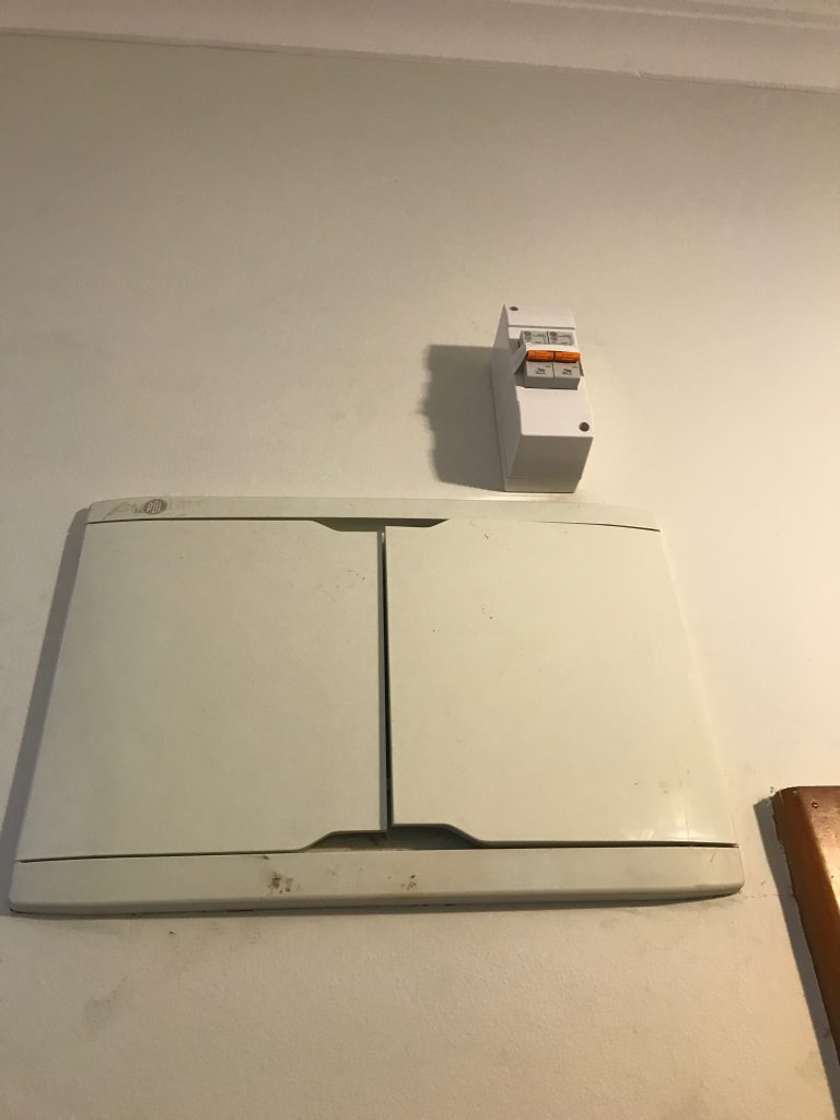
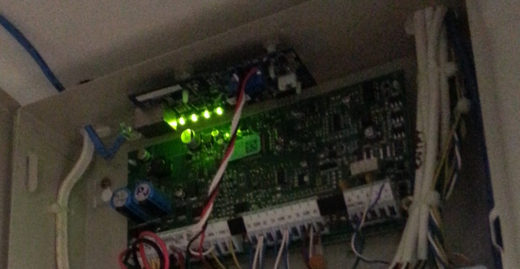
We also kept the ability to be able to failover to the element inside the hotwater cylinder. The electrical circuit has a bypass switch to flip between either the heat pump, or the cylinder’s built in element if a fault ever occurred with the external heat pump.

So far this solution has been working really well, power bills are low and the reclaim unit is very quiet outside. In fact, with the move from gas to electric, our household energy bill decreased on average, despite electricity generally being quite expensive here in NZ.

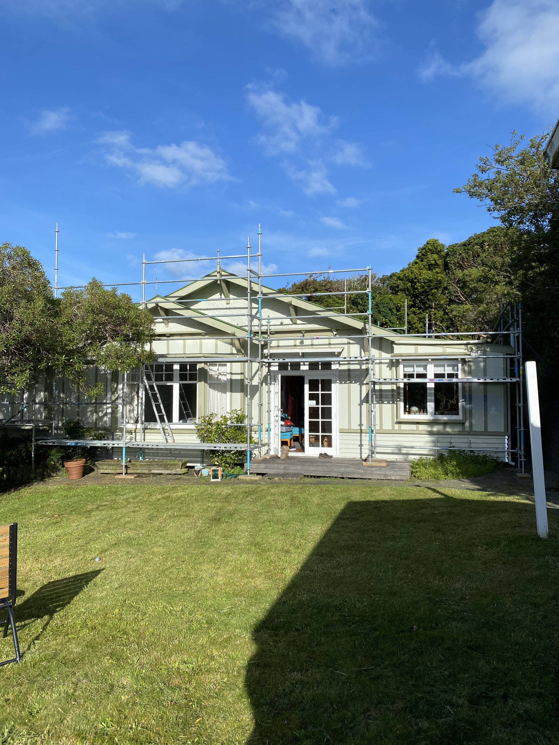
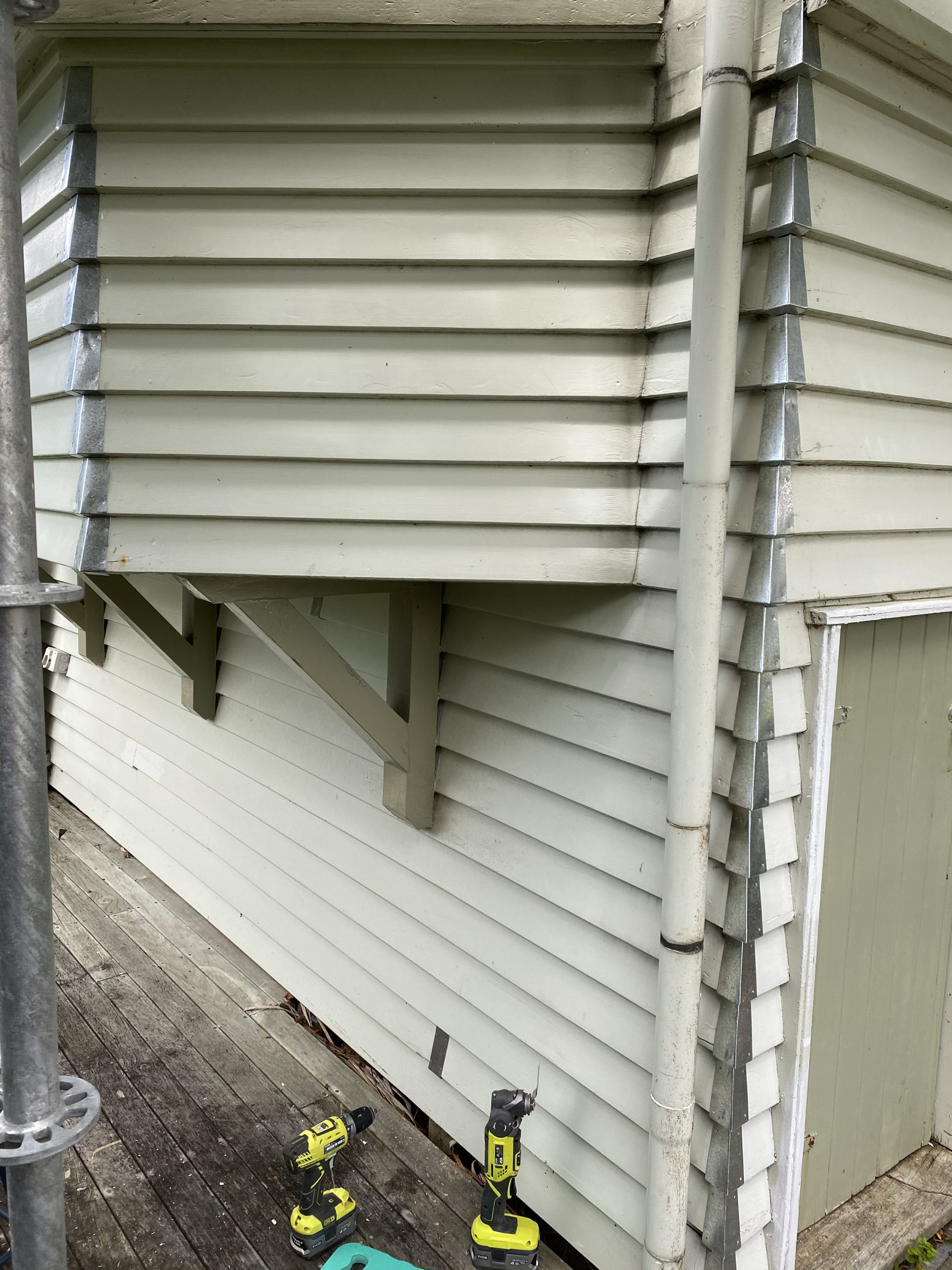
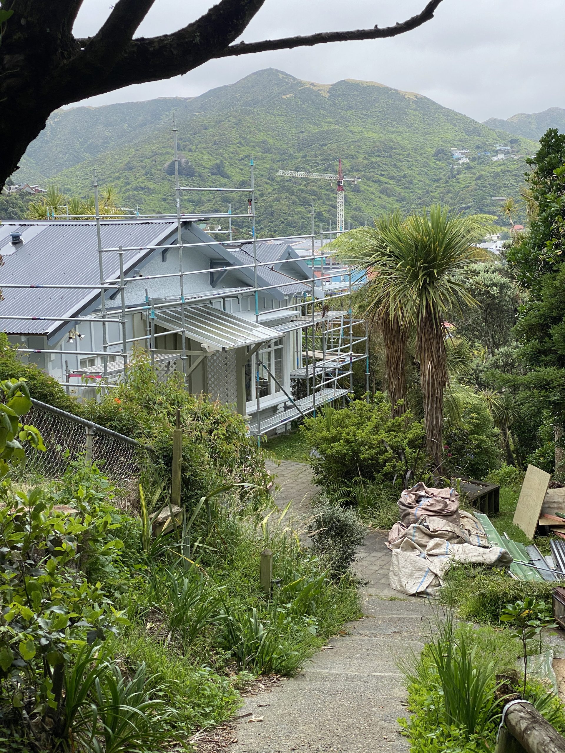
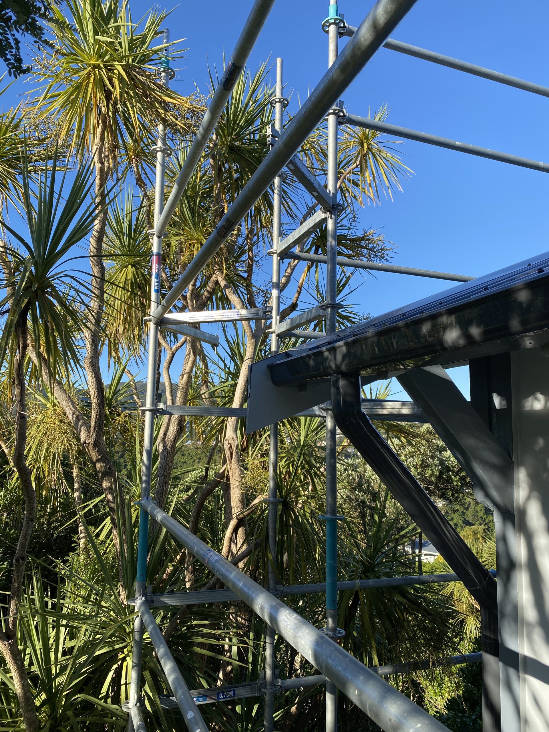
We then had the scaffolding put up. We were going to need scaffolding edge protection for the roofing work, so decided we’d use the opportunity to also get the house painted which meant scaffolding and walkways around the house.

Scaffolded and ready for re-roof and re-paint
Whilst a single story, the back side of the house is high enough we ended up with a three story scaffold. The cats found this whole assembly very enjoyable and spend more than a few nights climbing all over the place.

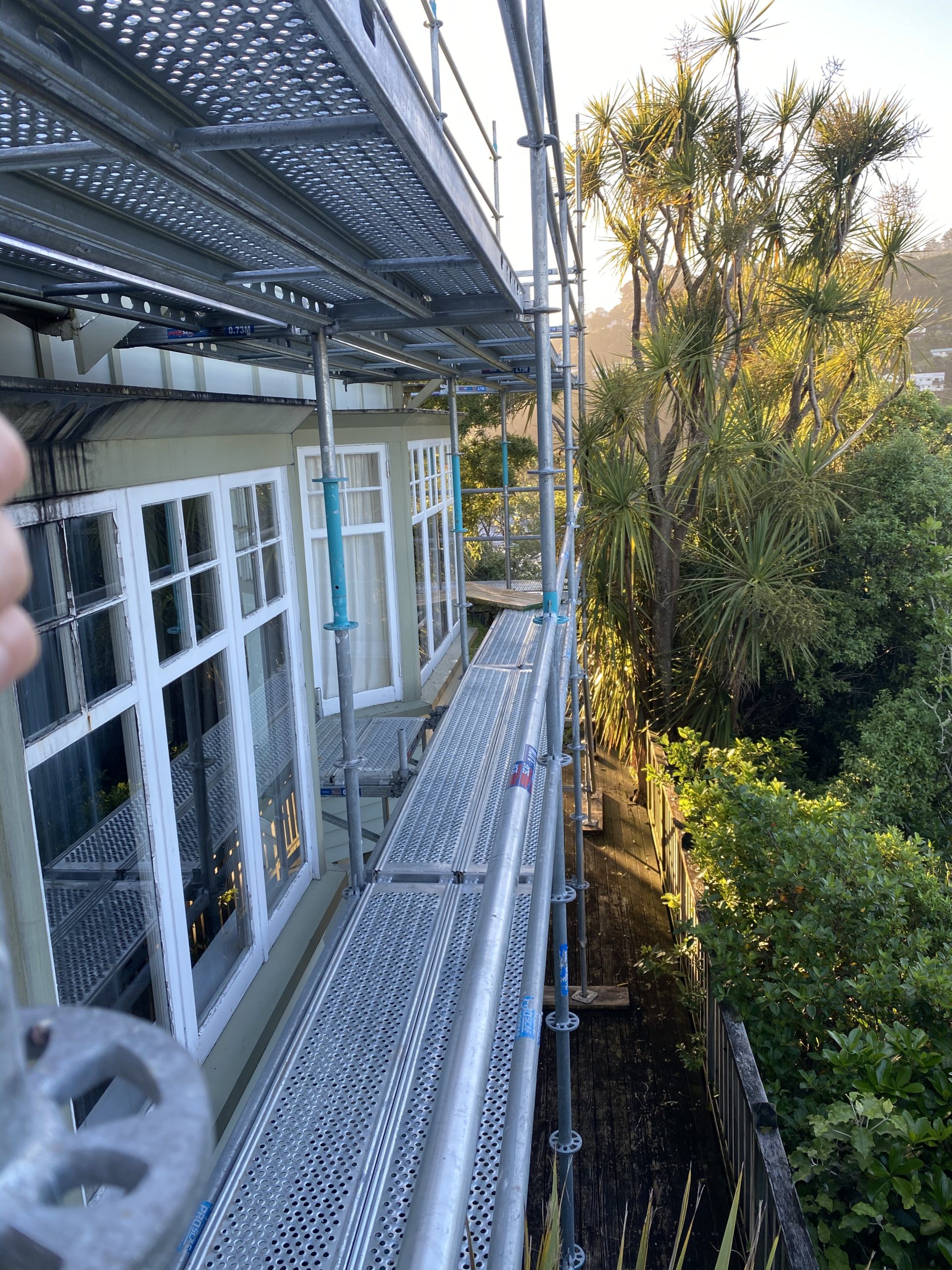
Due to some poor organisation with the roofers, the project was supposed to be finished before xmas but ran over into the new year which lead to the frustration of paying extra rent on the scaffold over the holiday period, but it did give a good opportunity for me to use the break to fix up various carpentry issues before the painters came and started.

A whole chunk of the bargeboard came off when removing the old roof, cut a segment to replace it.
Our weatherboards are generally in good condition but had a few areas that needed attention.
I also installed corner-soakers, these small metal pieces that protect where the timber weatherboards join to stop water getting in. Primed them all with metal primer before the painters came and did a full paint of the house.
The butynol on the window boxes didn’t need replacing but it has been prone to causing dark streaks when there’s rain runoff. To fix, used the opportunity to apply a butynol primer and paint coat to seal the surface and stop streaks.

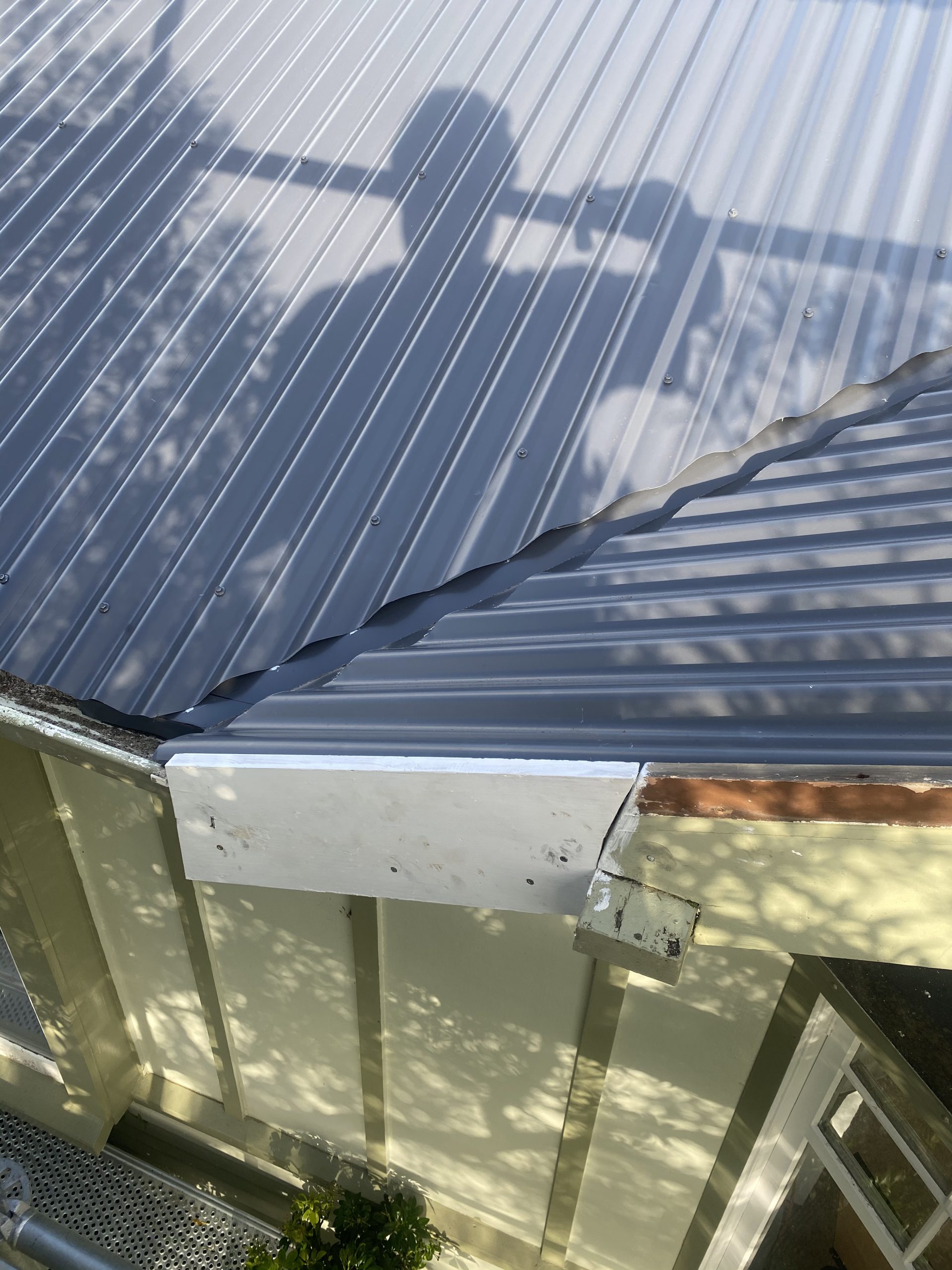
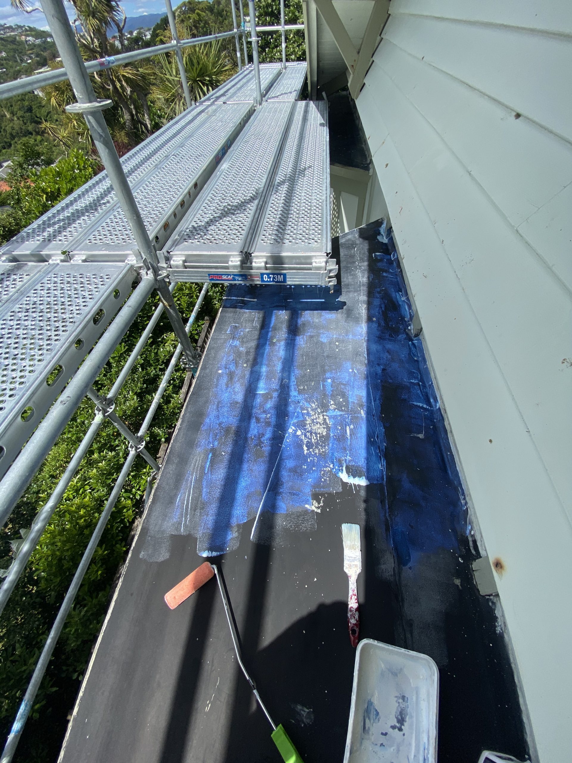
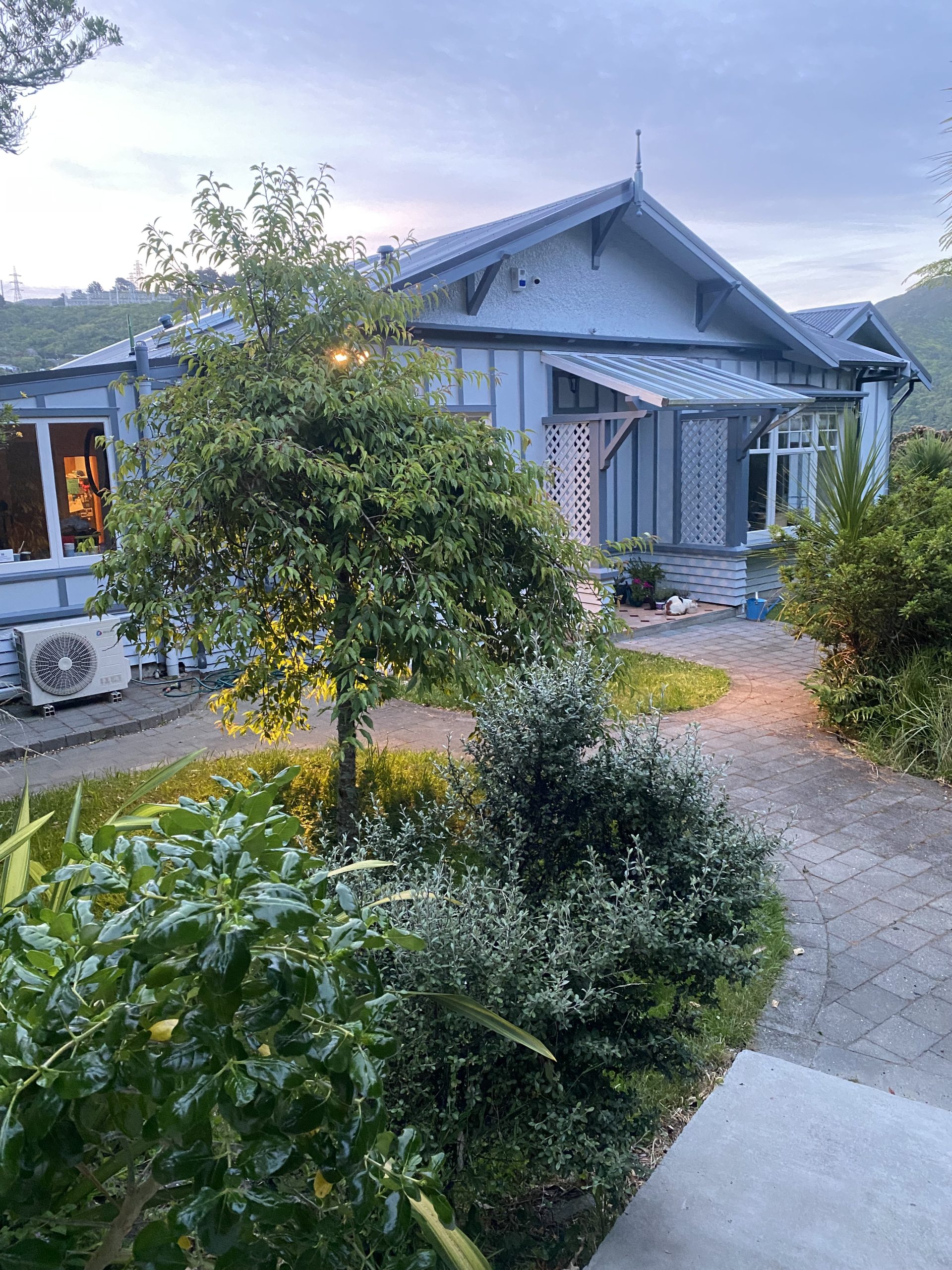
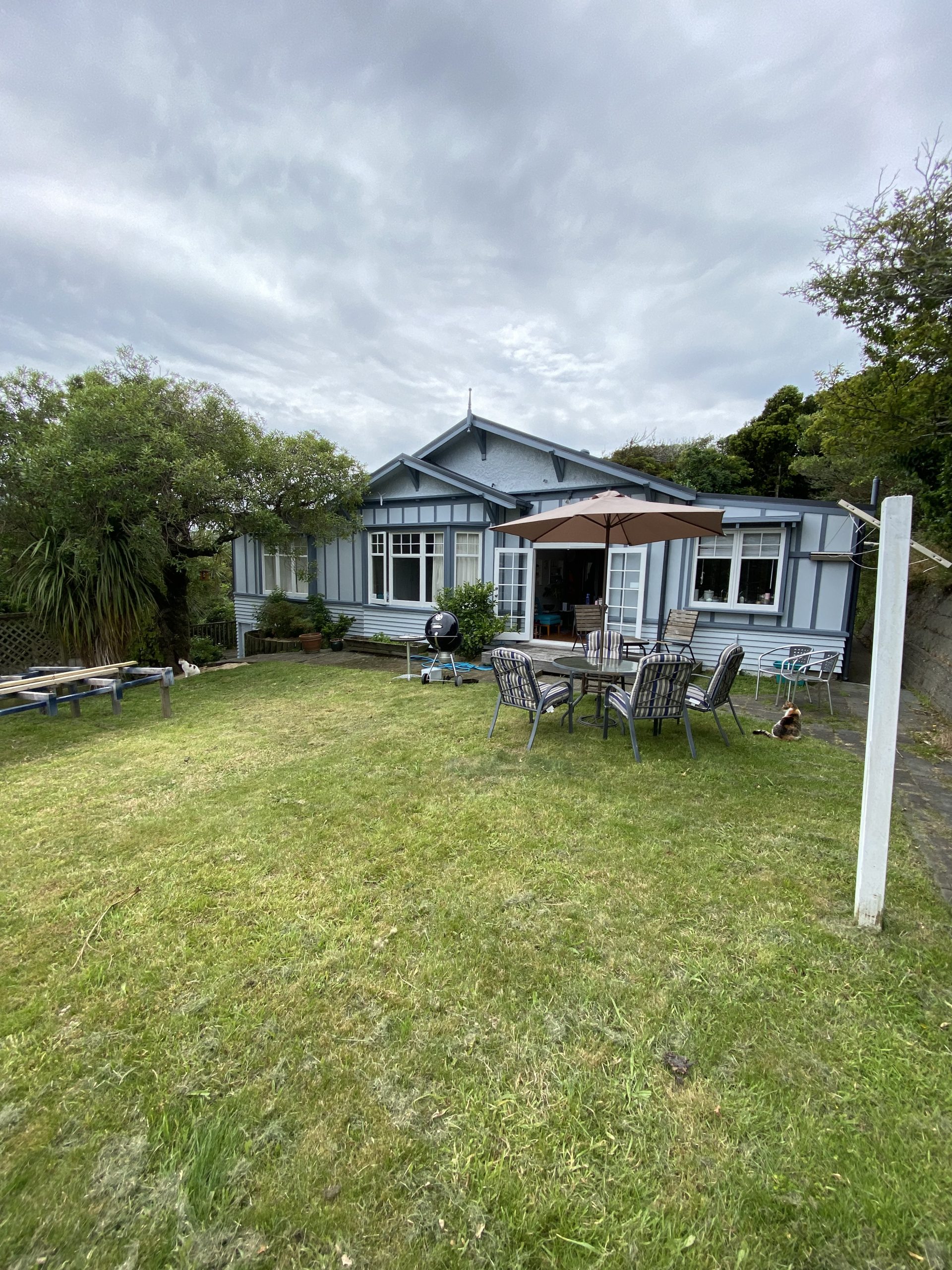
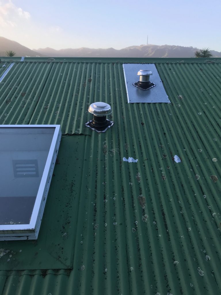
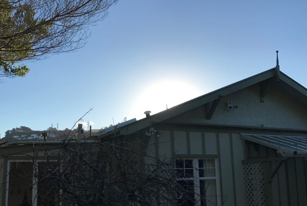
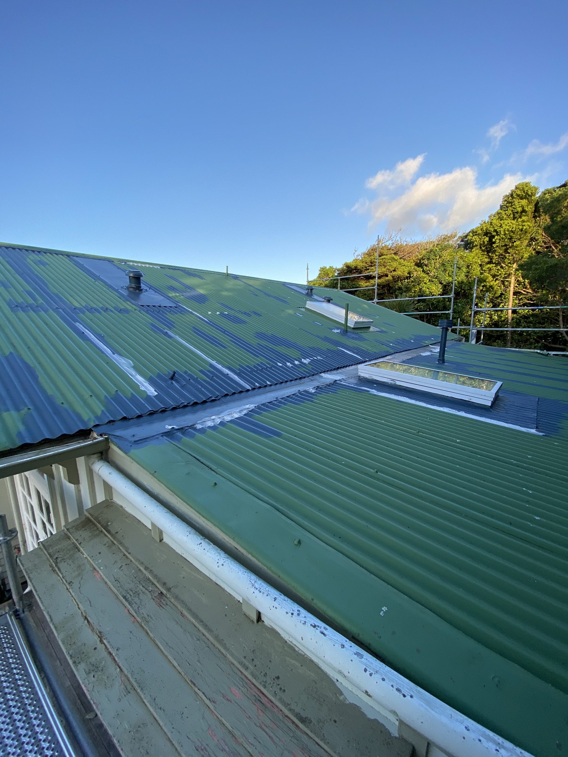
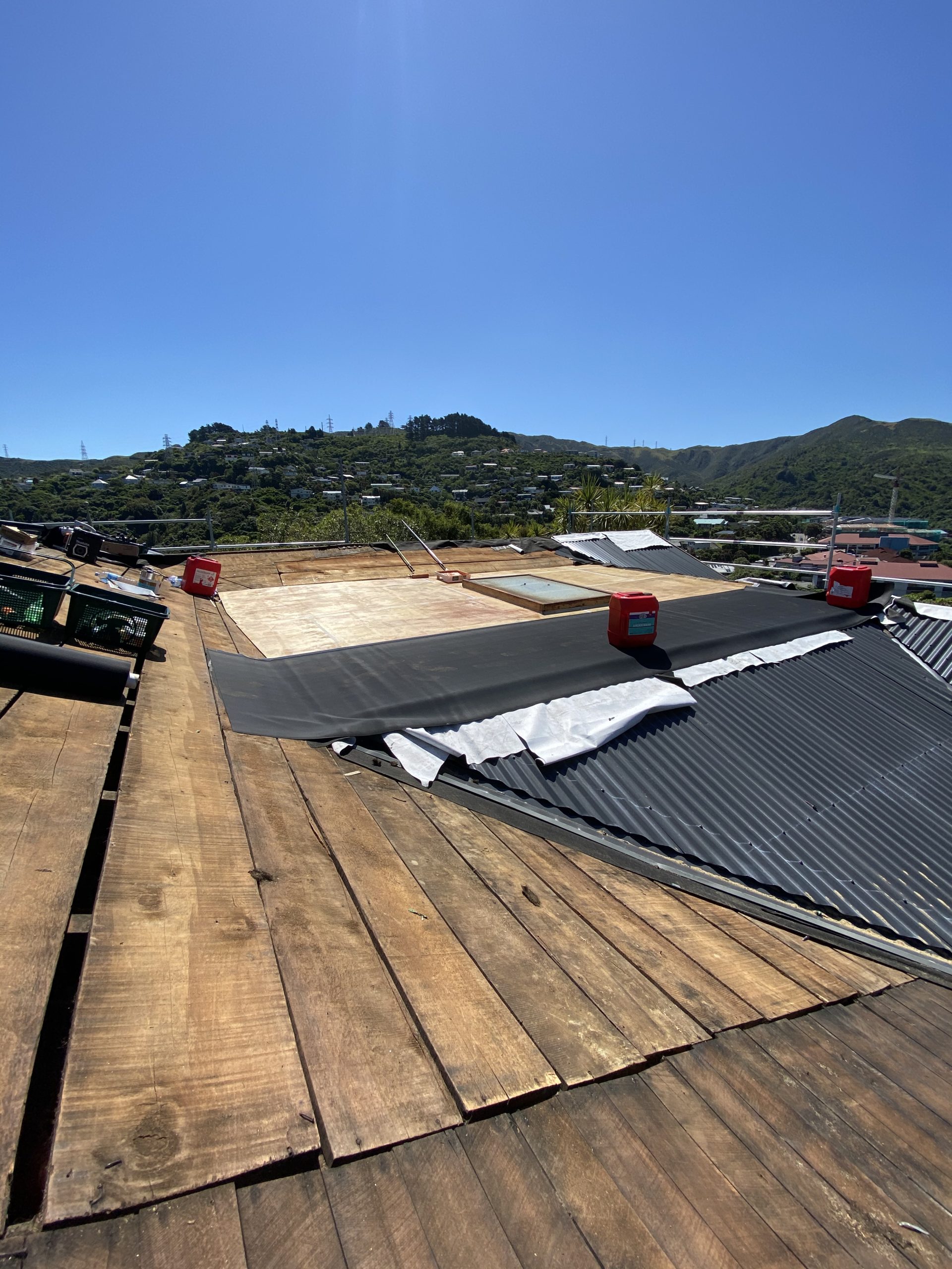
Whilst it took much more time, unexpected water ingress and stress than it should have taken, the end result of the re-roof is excellent. Our roof line is particularly complex and we have plenty of gullys and also a large butynol area in the middle that needed a full replacement.

I found our contractor super tough to deal with due to poor project management and comms but they sure did know how to build a roof. Checked everything against the NZ metal roofing spec and it all looks like they’ve done everything perfectly to code. Crazily enough, replacing an entire roof in NZ? No building consent required! So the home owner really is reliant on trusting the contractor to do the job properly and/or being capable of researching and validating themselves.

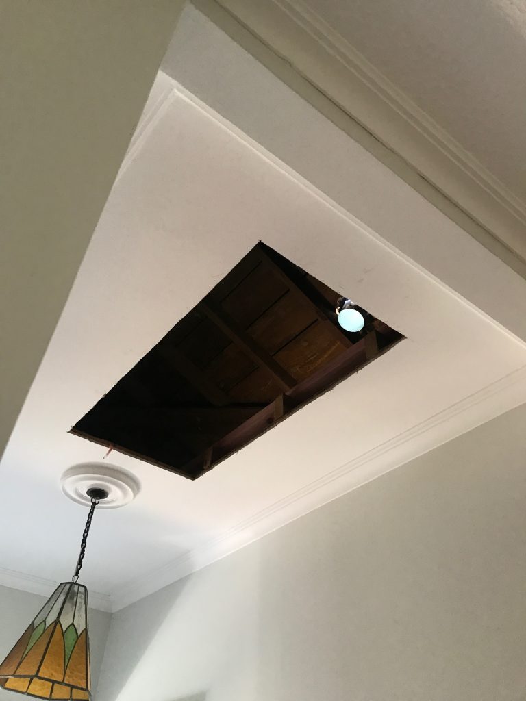
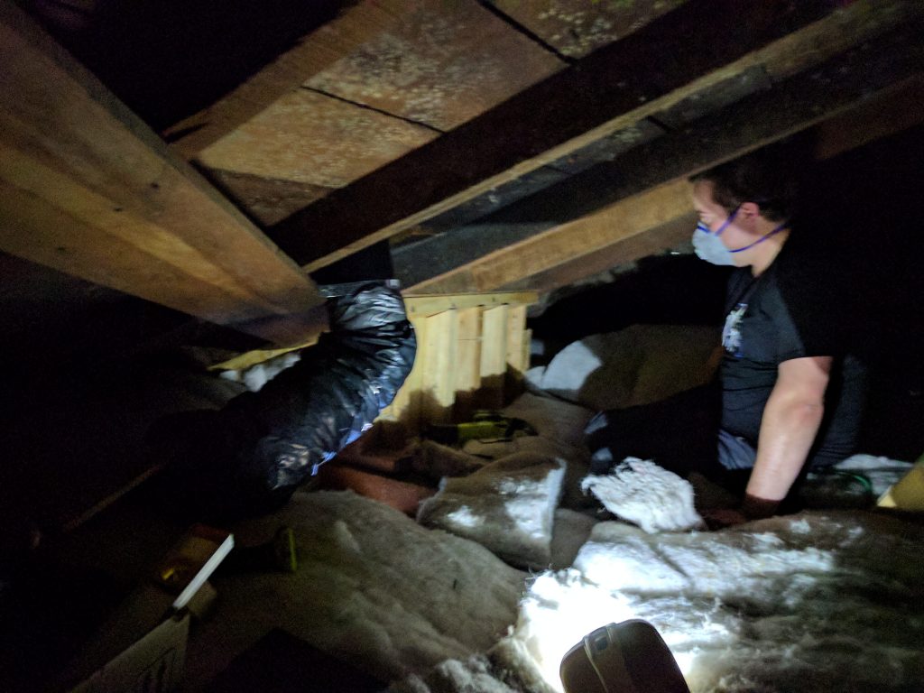
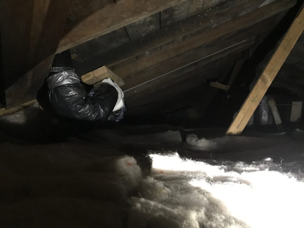
Most our entire roof is sarked (covered in timber) which made it easy to get around and work on it. And we had some other good luck, all the timber surface was still in excellent condition and didn’t need any work – with the exception of the butynol section that had been installed with ply that was too thin and so we had it upgraded to the proper standard.

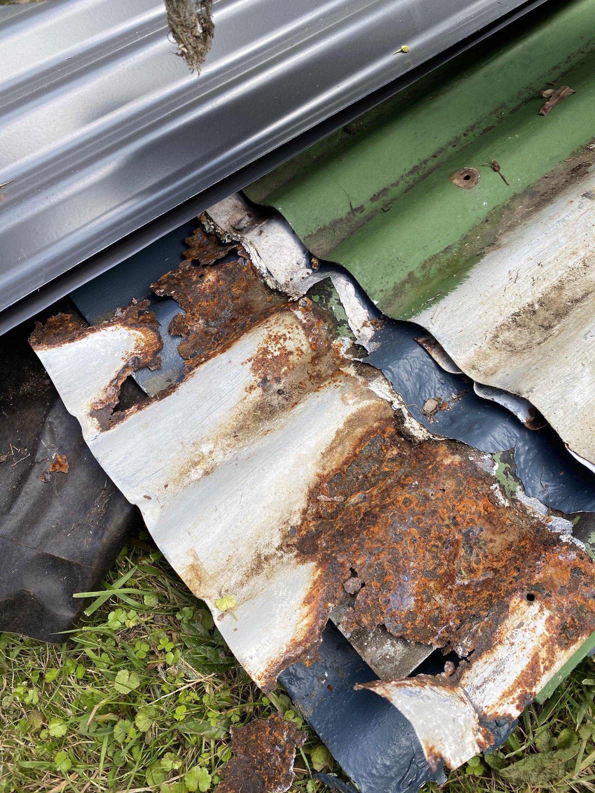
It looks like a lot of our roof was still original, with the roofers pulling off heaps of horsehair underlay that has probably been there for close to 100 years. The steel sheets were super thick as well – in many ways the sheets themselves were fine, the issue was with rust around all the nail points and where the sheets lap/join. Over the decades water had gotten in and caused some serious corrosion in points.

New vs old steel
Example of how weird our roofline gets
New roofline nearing completion whilst in mid-paint
View of the new roof and the new paint scheme in action
Lawn suffering the effect of having steel sheets sitting on it for a few weeks.
Nimbus exploring the roof

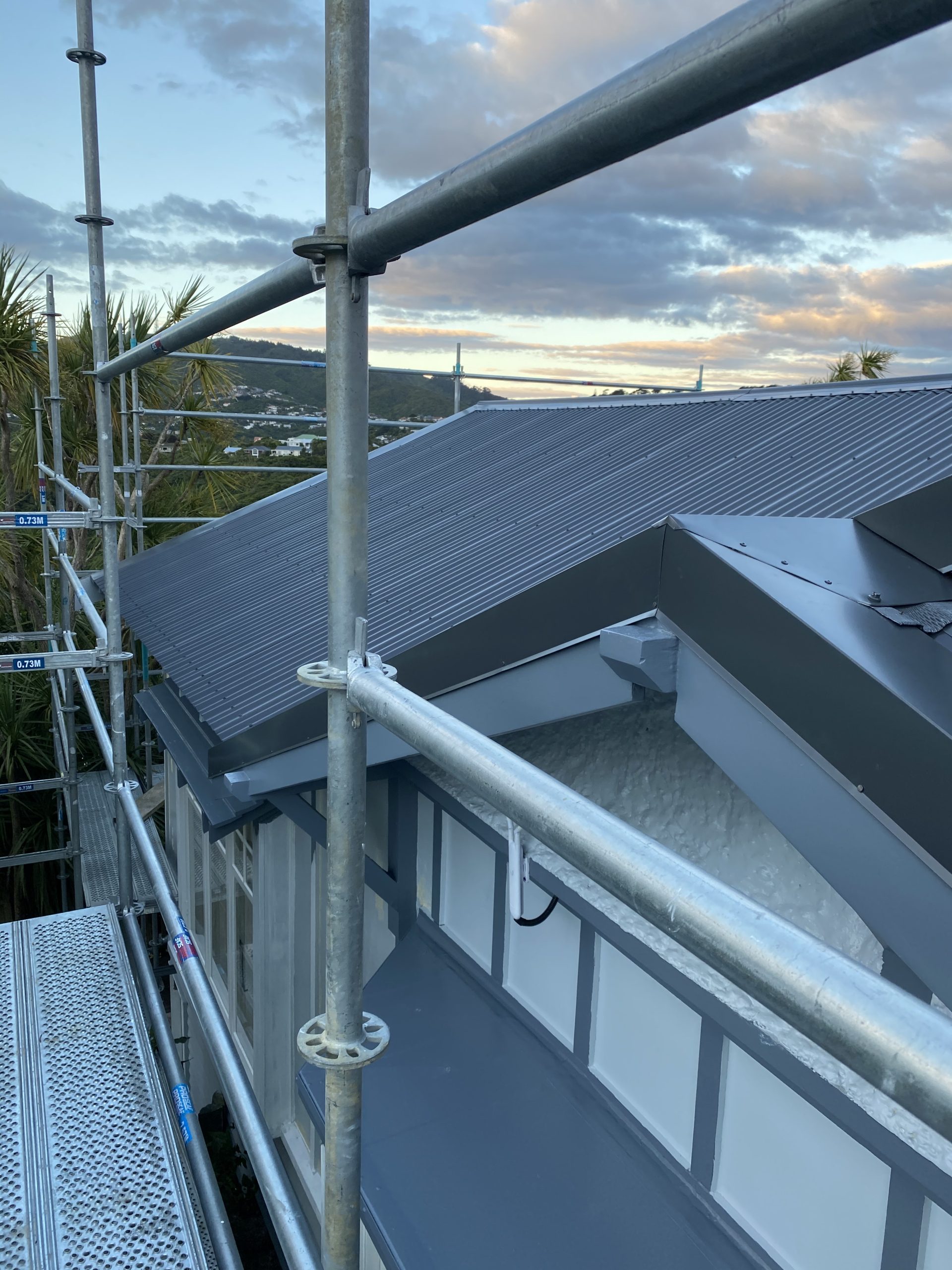
The new roof is all done in pre-painted steel so there’s no painting needed for the first 15 years of the roof. It actually looked so sharp I felt bad that I was intending to keep and re-paint the beat up old gutters, so I ripped them all down before the painters arrived and then installed new ones myself at the very end of the project.

I ended up using Marley Stormcloud spouting which conveniently comes in a range of pre-coloured options that matched our roof and wall colours. There’s also a heap of good materials from Marley on how to install it, with the house being fully scaffolded I was able to do it with some help from mum in the course of a weekend.

Spouting lego
Cutting gutter segments to length
Installed gutter and spouting

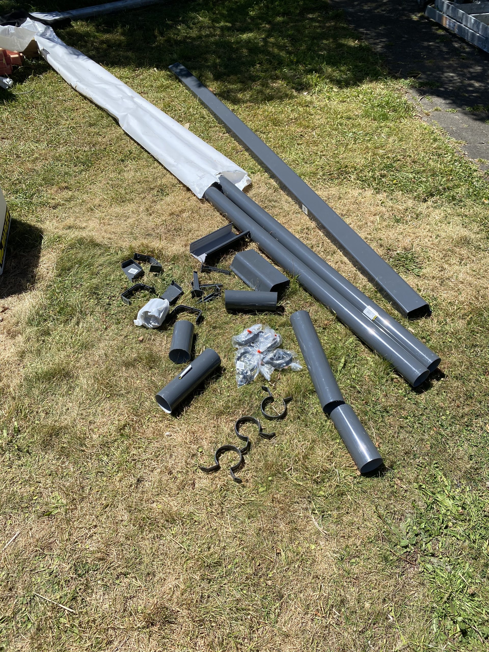
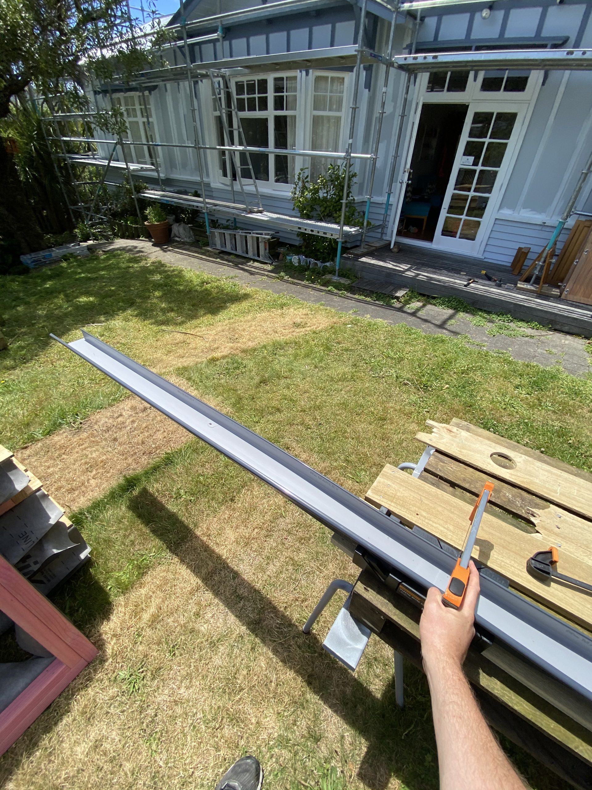
And like the roof, the spouting being pre-painted saves massively on the labour and hassle and looks far sharper than anything I could achieve with retrospective painting.

Speaking of painting labour – the amount of work that our painting contractor put in was incredible. The cost of painting a whole house in NZ is eye watering but at least I could see where my money was going with this crew, there was so much prep work fixing joins, rust spots, sanding, etc before the actual painting started. Took a crew of 2-3 people about 2 weeks to do the whole house. I used Graham’s Painters in Wellington and was really happy with them.

With the roof, gutters and paint being done, naturally I decided to squeeze in a few more projects for the summer.

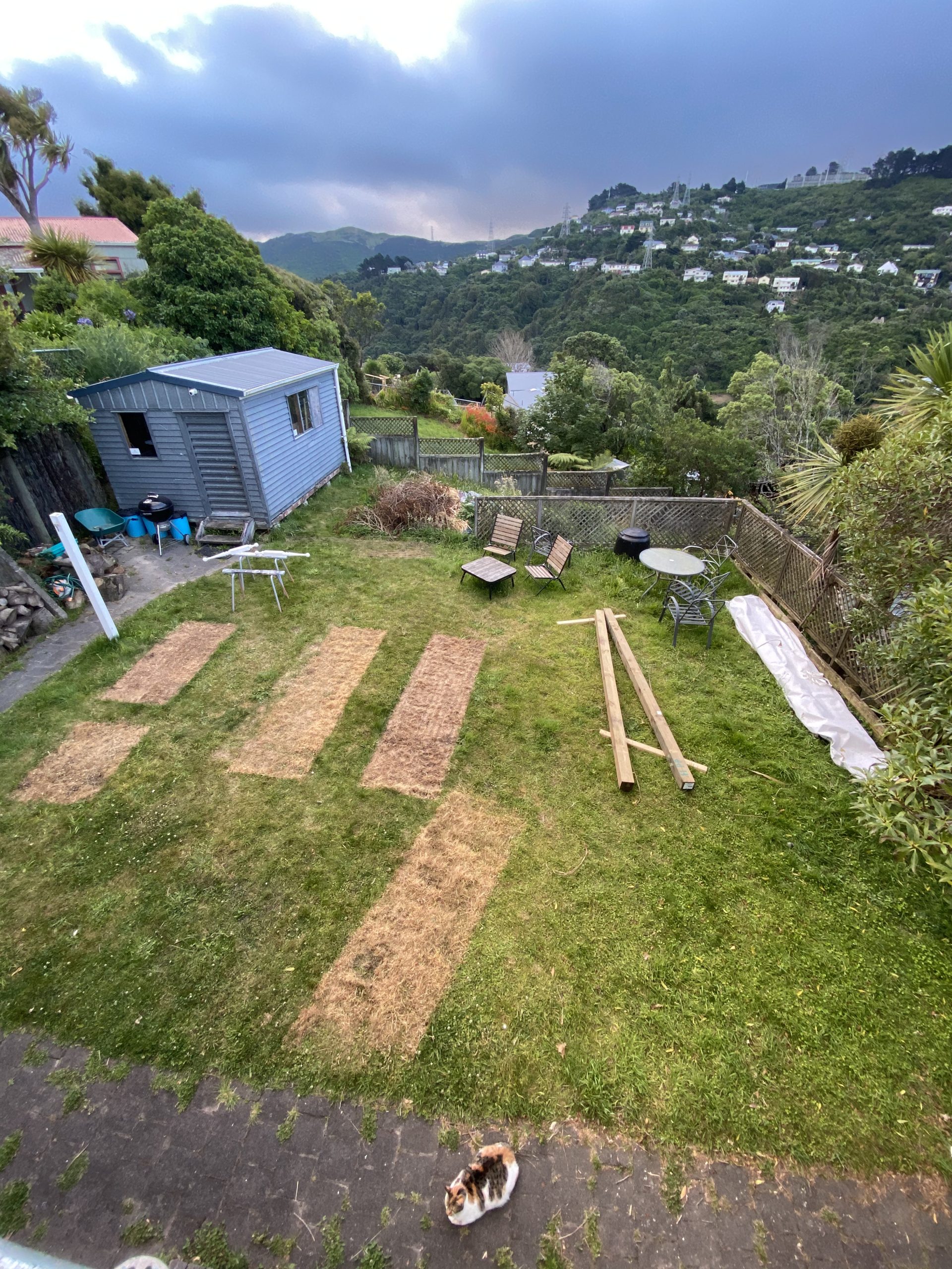
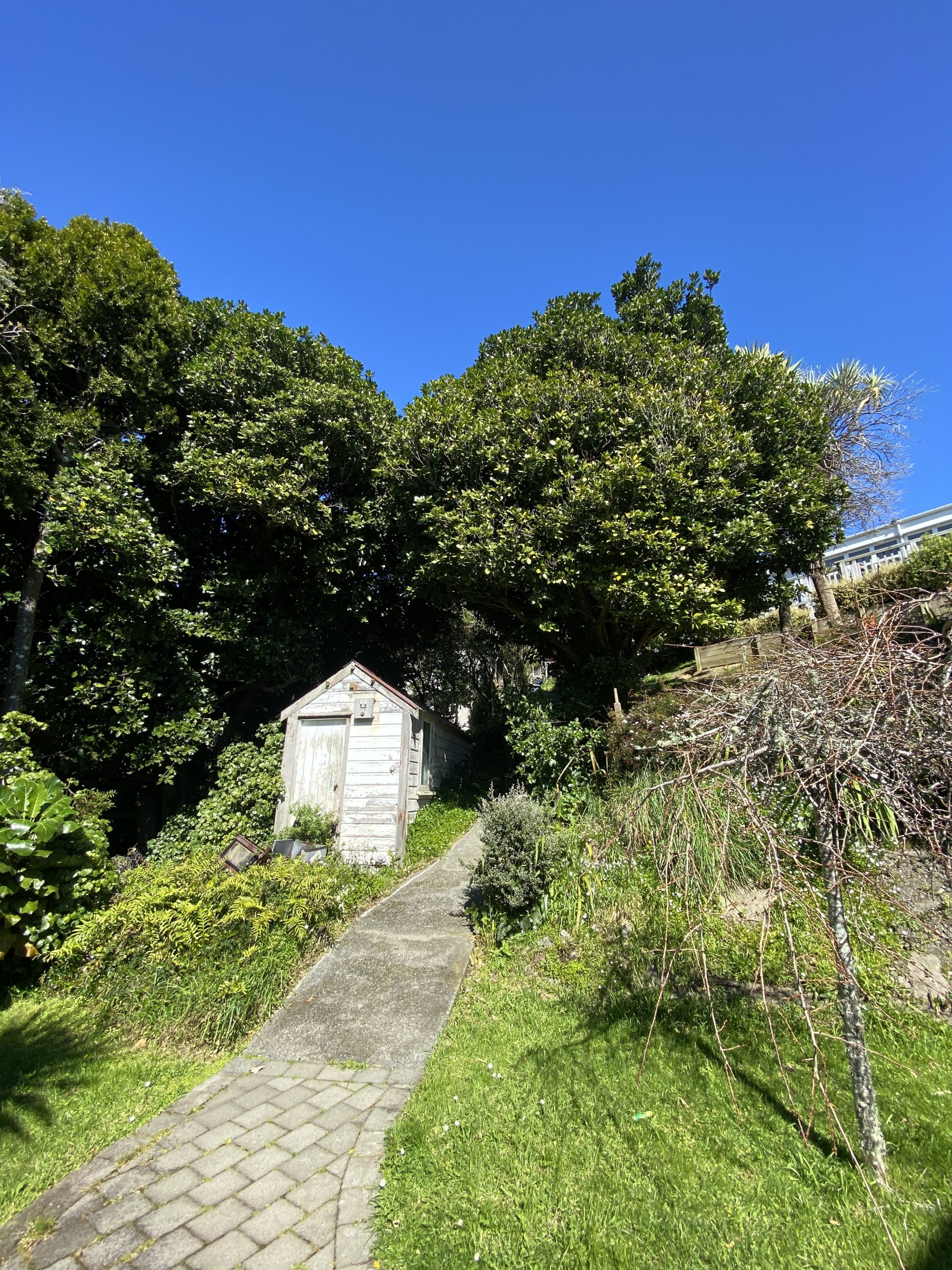
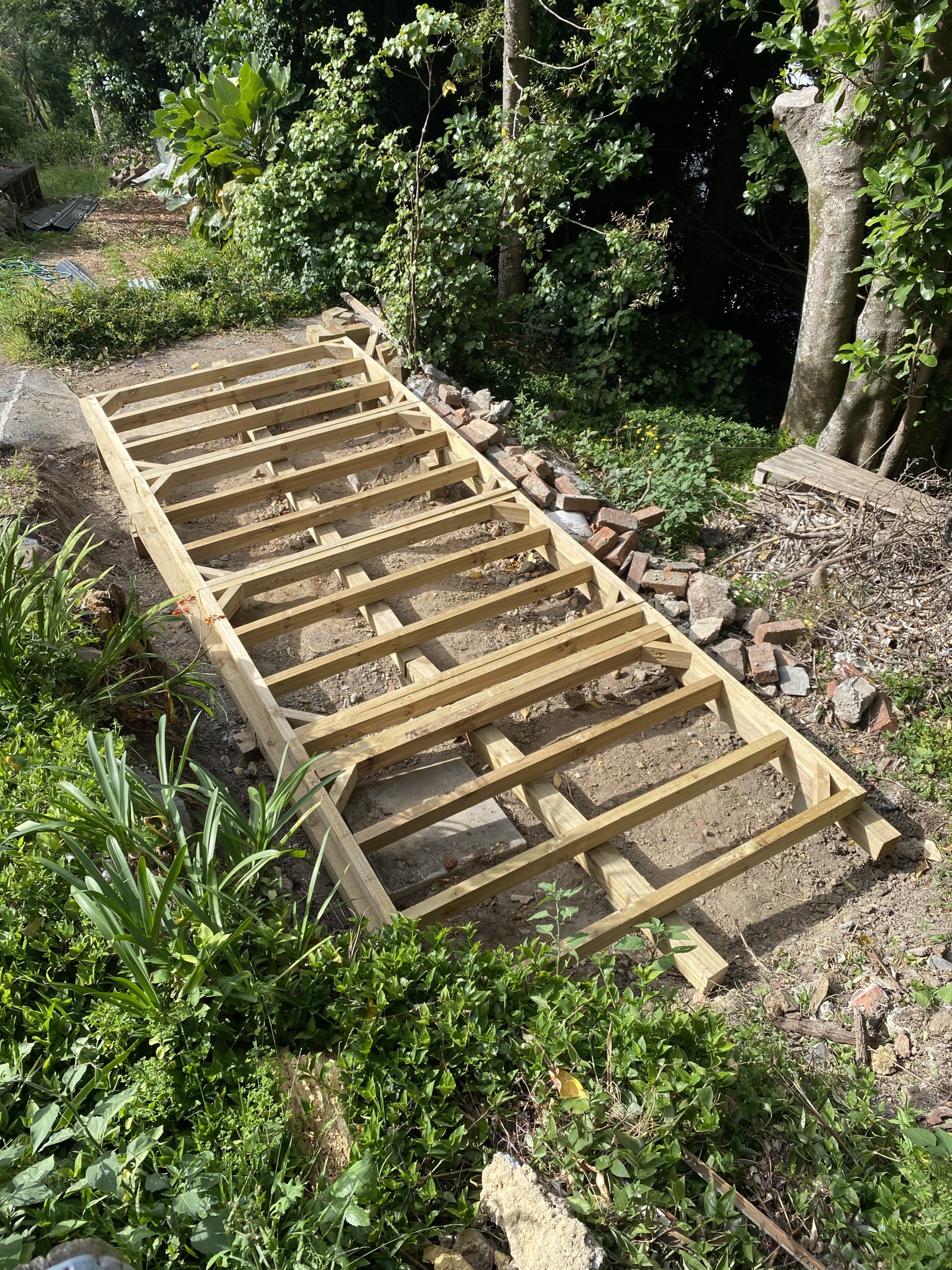
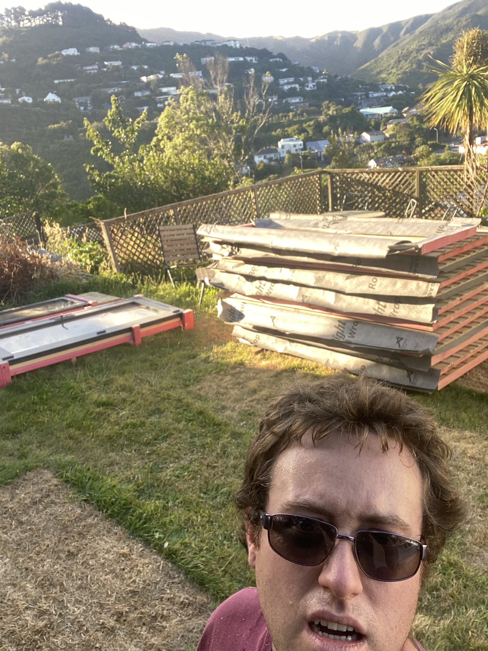
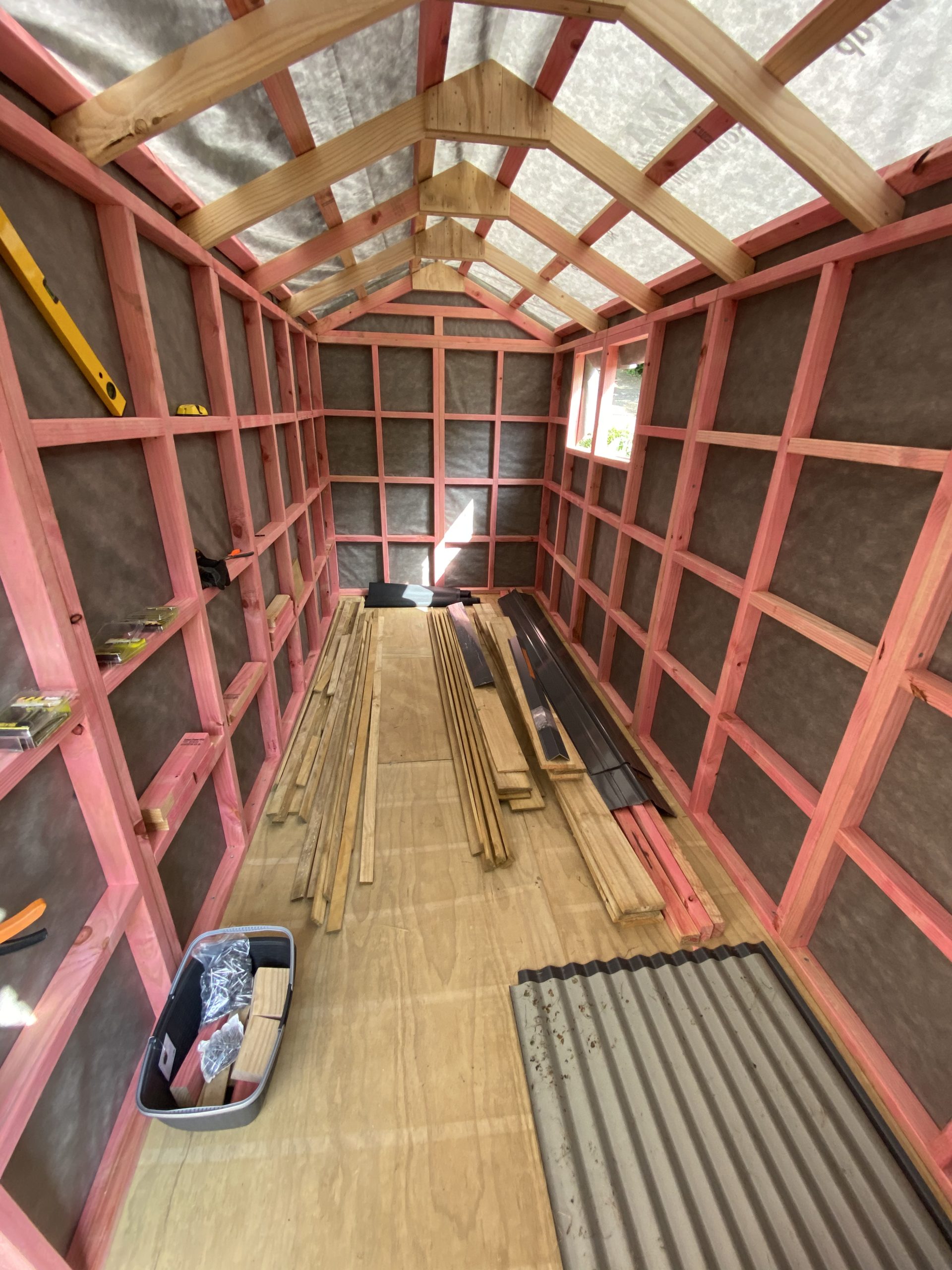
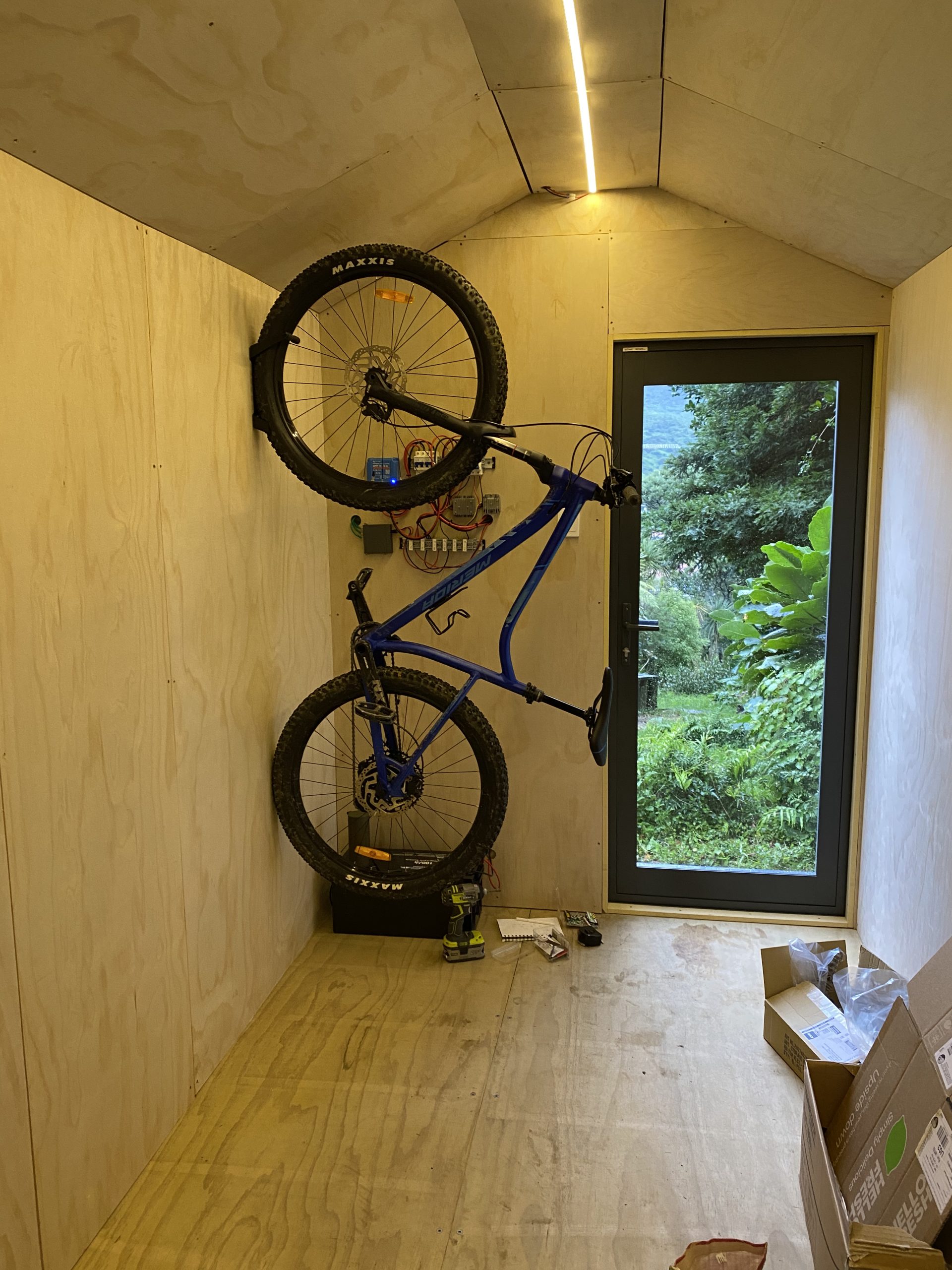
Lisa, having got tired of having now 3 different bikes inside the house, gave me an ultimatum that I needed to fix the old shed before I could buy any more bikes. Having looked at it in detail the verdict was that the old wash house / front shed was too far gone to simply repair and I brought a new made-to-order kitset shed that matched the original’s dimensions exactly to replace it. The team at Sanders Cabins & Sheds was able to alter the dimensions of their off-the-shelf product slightly and position the window/doors at the specific spots I wanted which was excellent.

The original wash house for the property. We also took the opportunity to drop the massive karaka tree on the right to really open up the space and trim the neighbours one on the left.
New shed floor going in on the footprint of the old one. I spend 2 days just digging the post holes to get these foundations in.
It took 5 hours for two of us to carry down all the shed pre-fab modules, the H5 piles, concrete and plywood interior.
Kitset shed finished except for the steel roof. The steel roof seems simple but that took another couple of days just to be able to get the sheets aligned right with the awkwardness of the location making climbing on the roof difficult.
Testing the shed for bike fit. Oh and did I mention the 2000Wh solar setup that I added to run the cameras, security, lighting and e-bike inverter?
Having dropped the trees and had the scaffolding picked up, we got a contractor in to re-surface the path (significantly cheaper than a full replacement of the slab)
New shed, new path and a few less overgrown trees

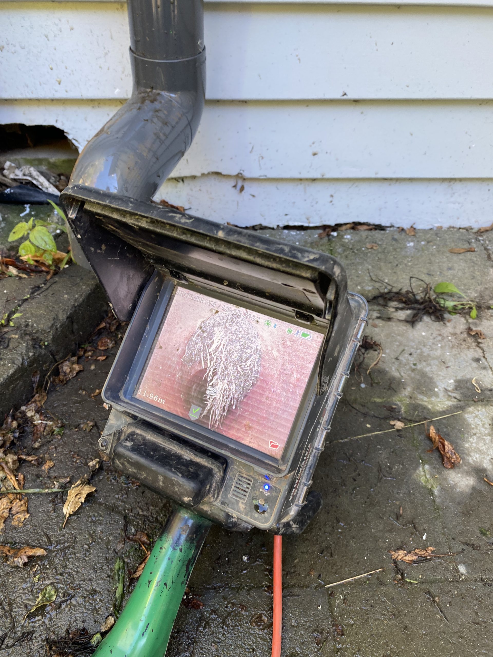
With the shed done, what else? Well we had a slight side quest to dig up and fix a segment of the sewer pipe. Like most activities that involve me digging, it took about 2 days of effort to get down 1.5 meters to where the pipe was located, but that sure bet the thousands it would cost to remotely re-surface the pipe.

Not sure those roots are supposed to be inside of the pipe…

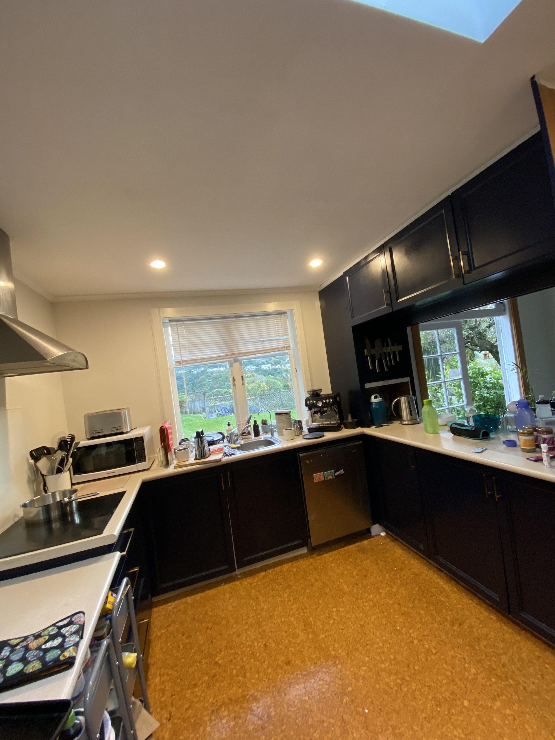
And I had to learn how to plaster to fix the previous massive missing section of the kitchen roof that was damaged by the old roof leaking. Oh and you might notice that the kitchen has changed colour, that’s thanks to Lisa pulling off all the doors and painting them as well as fitting new handles.

New interior roof, new paint job. Still yet to replace the cork flooring, but it’s on the list…

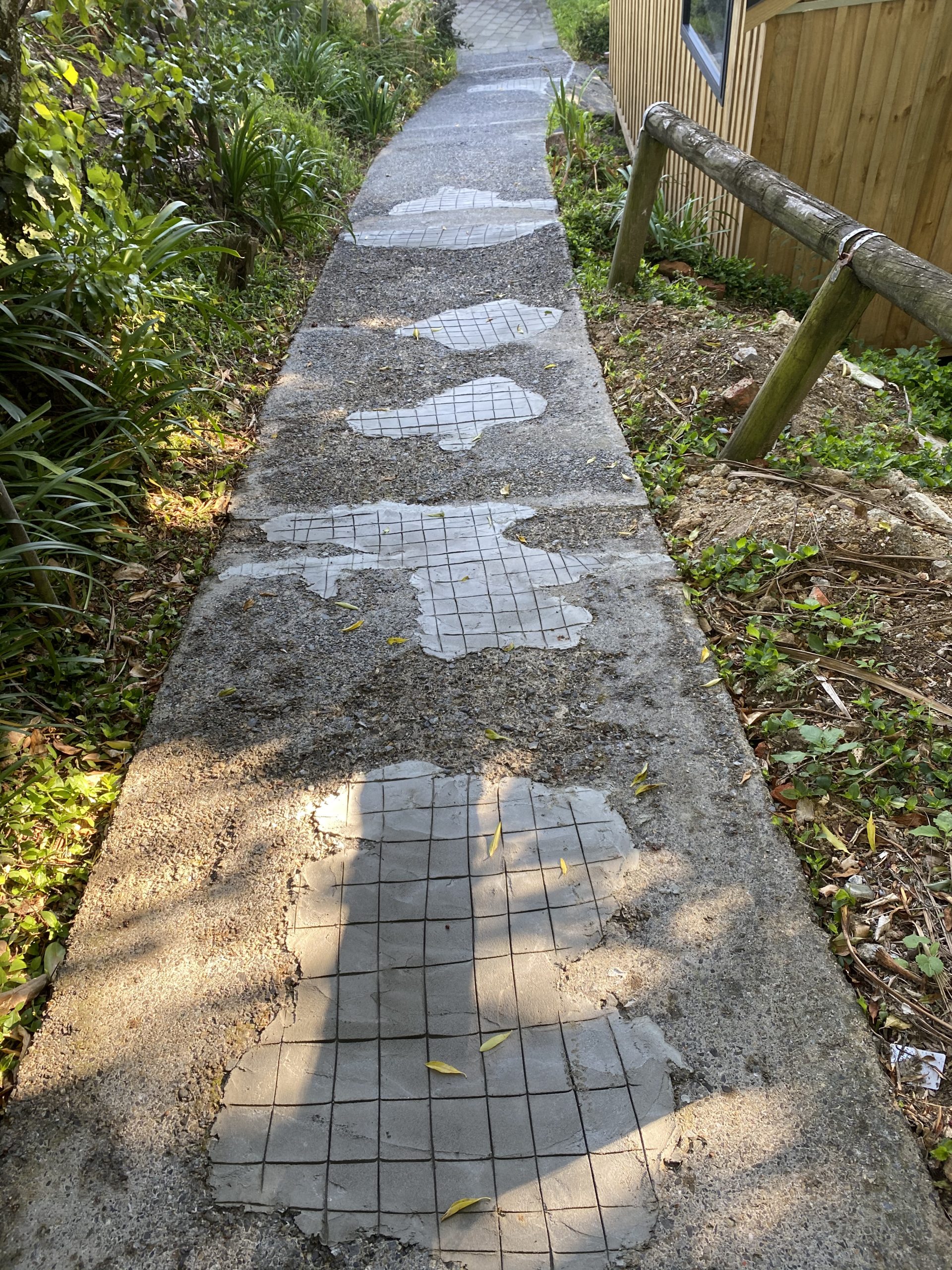
We managed to complete the full set of projects (roof, scaffold, paint, path, shed, hot water, cooktop etc) for a bit under $100k NZD, but this was possible only by doing a bunch of stuff myself like the gutters, plastering, shed, digging and house carpentry. I had estimated that we’d run about 20% over budget with unexpected costs and that ended up being almost perfectly accurate. Stuff like higher than expected electrical costs, the decision to replace the gutters, other miscellaneous materials, etc.

Being smart about sequence of work events and shopping around for trades also helped massively. For more than one of the trades we received quotes that were twice as high as the ones we eventually selected. Sometimes you get what you pay for, but sometimes people are just taking the piss. Worth shopping around for these big ticket items.

My favourite was the painter who came to quote and turned up in a huff because he couldn’t park right outside the house (he just parked his ute on the yellow lines anyway like a classic tradie), proceeded to diss the house as “needing a lot of work” infront of me and then quoting twice as high as another firm. For some strange reason he didn’t get the job.

Finally, having finished up the bulk of this project I treated myself to a new car and made sure to get out a heap to make up for the prior summer being consumed entirely by the renovation chaos.

My new Ravioli off on an adventure
Relaxing after a 90km round trip around the Rimutaka-Wild Coast trail.
Hitting the Makara Peak MTB trails

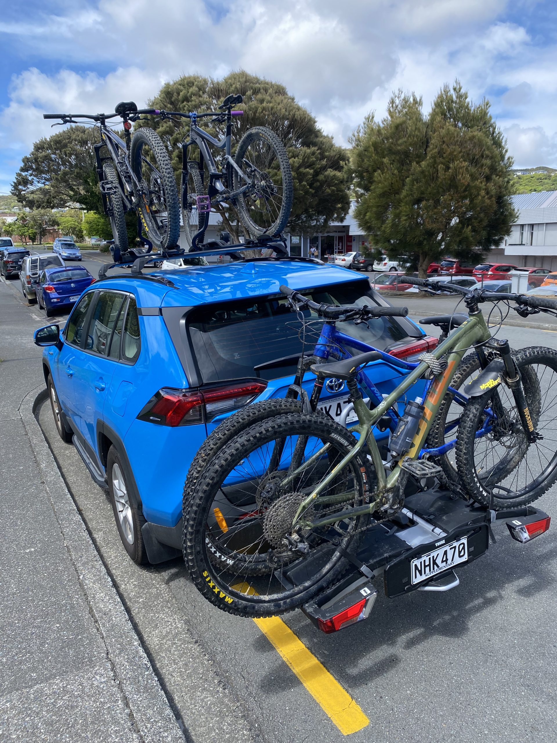
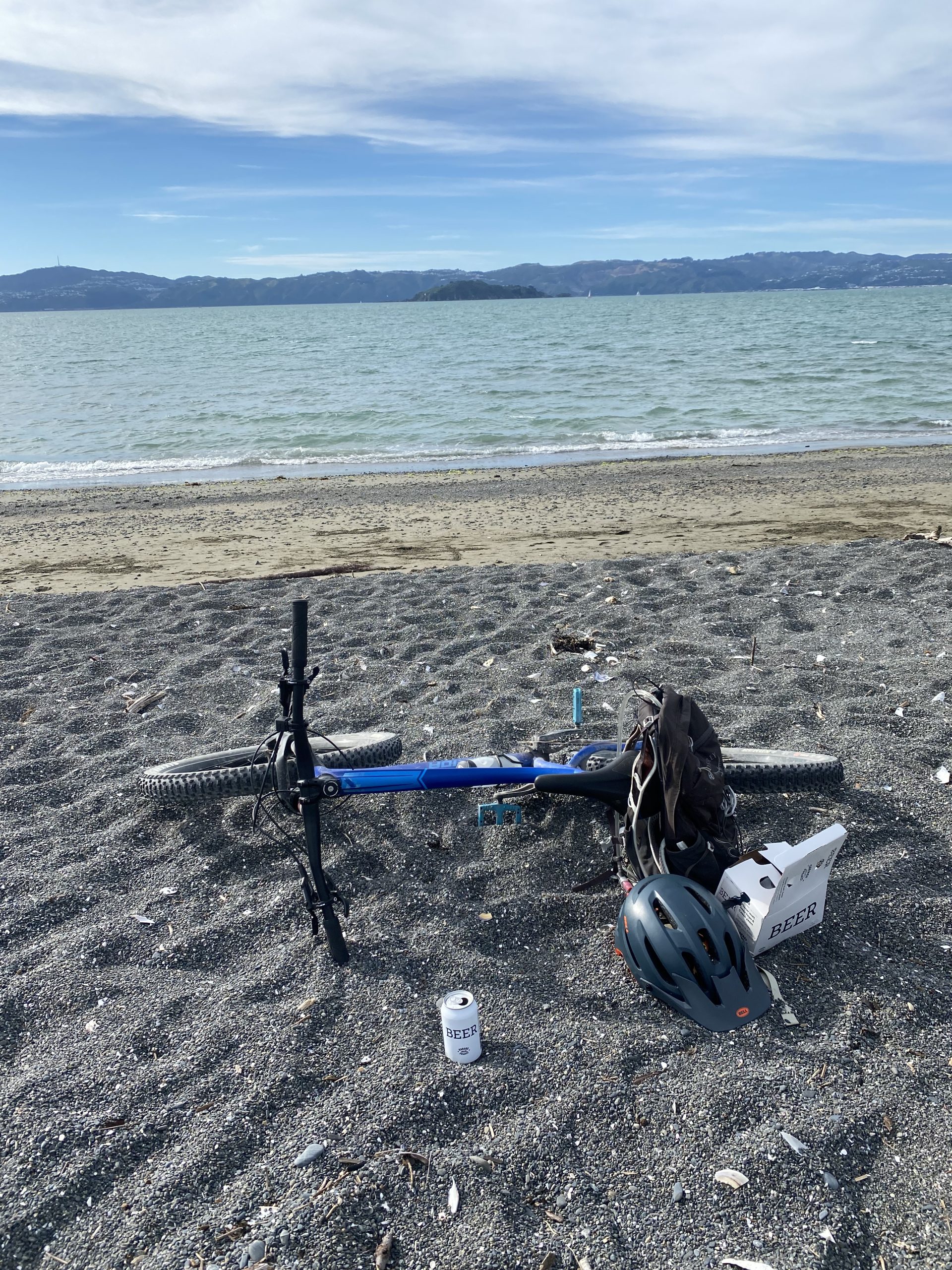
Aside from it’s bike carrying capabilities and gas thriftiness, one of the big aspects of buying the RAV4 2021 Hybrid was getting something with AWD for handling the mountains in winter – and then promptly only managed to spend 1 day up the mountain thanks to COVID-19 lockdowns. But I’m ready for 2022 season!

A perfect day on the mountain in 2021

Where does this leave the house? In a pretty good state now. There’s always something more of course, I have some interior work to finish off and it’s looking increasingly likely that we’ll need to do a bathroom replacement in the next few years due to everything starting to reach end of life in there, but all critical stuff is sorted for now and we’ve gone through 2 winters now without water coming through the roof anymore which is nice.

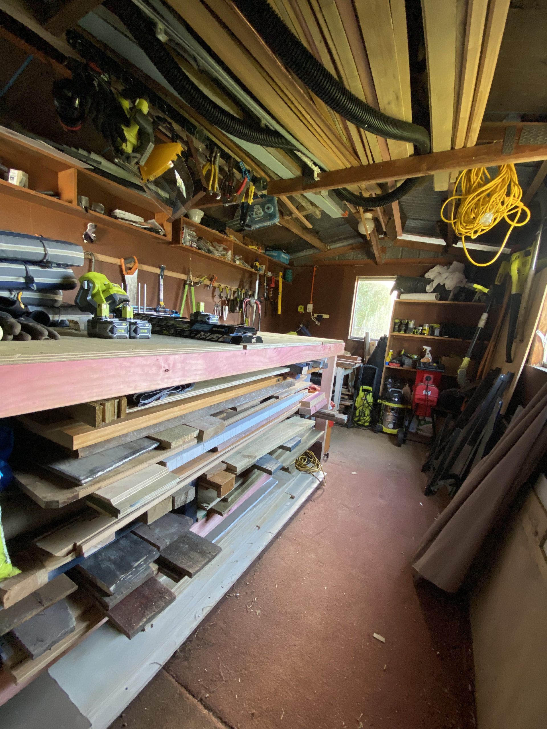
And I got my bike shed at last! Which has been wonderful, finally cleaned all the junk out of the laundry and have a proper space for bike tools, parts and of course the bikes themselves.

Added some garage carpet to make it feel extra homely

I’ve even cleaned up the older tool shed so it’s actually possible to navigate and find things in there, so that makes two quite usable spaces which is really handy given we have a smallish house at around 140m2.

Downside of an older house.. this shed is almost entirely just tools and materials needed to maintain the house and property. So you get a cool shed but… end up filling it with stuff just to look after the house.
Completed view of the front of the house
Completed view of the back of the house

Introduction to Xiaomi Zigbee IoT/Smart Home devices

I’ve recently been experimenting with Xiaomi Zigbee IoT/Smart Home devices. These devices are super affordable (approx $20-55NZD) and make it very easy and affordable to upgrade a home with useful smart devices.

My plan is to do a more detailed blog post at a later stage, but if you’re interested in learning more, I recorded a talk I made at the Wellington Home Automation Meetup a few weeks back that introduces these products and how I’m using them.


The Heating Project

Having gone through three Wellington winters in our home, Lisa and I really didn’t want to make it a fourth this year. Whilst our property is fortunate enough to get a lot of sun during the day, it still can’t sustain a comfortable temperature in the middle of winter when we have weeks with day highs of 10c and lows of 5c. In the worst case, it’s gotten right down to 2c outside.

We insulated as much as possible shortly after we moved in, both the roof and floor, but unfortunately with house being very low to the ground, there were sections of the floor that simply couldn’t be insulated, so we ended up with approximately 60% coverage. We aren’t sure about the walls either, some of the ones we’ve had to cut open to do work have revealed insulation but we don’t know for sure if it is fully present in all walls of the house or not.

Insulation upgrade in progress

Most New Zealand homes are also only single glazed and ours is no exception, which means even with the roof (100%), floor (~ 60%) and walls (??%) insulated, we still have massive bay windows leaking heat like crazy. So regardless of the natural sun we get, a high capacity heat source is still critical to maintain a proper temperature at the property.

Which is also precisely what we lacked – when we moved in the house had a rusted wood fireplace in dubious condition and an unflued gas heater which are generally just a bad idea all-round. Neither of these were safe options, so we needed to replace them with something better.

We considered a few different options:

  1. A new wood fire would offer a nice ambience, but access to the property is a challenge and we’d go through most of the firewood we’ve ended up collecting from dropping overgrown trees. So long term, we’d be buying expensive firewood and having to shift it onto the property – plus we’d lose a good amount of space storing a winter’s worth of firewood.
  2. A gas fireplace was considered due to us already having existing piped gas. A modern flued gas fireplace is efficient and doesn’t exhaust into the living space, plus offers all the classic ambience of a fireplace. The only downside is that the heat would be focused in our lounge or dining rooms and wouldn’t propagate nicely through the rest of the house. There are some models that feature ducting that can exhaust some of the heat to other parts of the house (eg 2 or 3 other rooms) but our size of property wouldn’t be able to get full coverage meaning we’d need to looking at needing to install two fireplaces or additional heating to fully cover the property.
  3. We seriously considered a gas boiler and European style radiators emitting radiant heat in every room. This would result in us losing some wall space, although we would have been able to put them under the windows. Ultimately this option ended up not being possible, as our existing gas pipe is too small in diameter and the cost of running a new pipe from the street to the house is extremely uneconomical.

The gas pipe limitation also impacted our ability to drive other high consumption gas appliances, for example feeding large fireplaces could be tricky and we’d probably be unable to run more than a single instantaneous hot water system. Probably for the better anyway given that it’s a fossil fuel, but it’s so much more cost effective than electricity on a per kWh basis in NZ that it’s a compelling option if you have gas piped to your property.

Given the above issues, the only remaining option that made any sense was electric heat pumps. Heat pumps are generally 300-400% efficient, meaning although they use super expensive electricity, you get very good heat output compared to running traditional electric heaters.

What most NZders will think of when you say “heat pump”

These are becoming quite popular now in NZ as an affordable upgrade (a fully installed basic unit might cost as little as $2-3k NZD) for existing properties – the purchase of a mini-split system such as the above allows for easy retrofit installation and you’ll often see these added to lounges to ensure a reliable heat source in the main living space.

Their weakness is that you don’t get the heat spreading from the primary room out into other parts of the house, such as bedrooms. And they’re not cheap enough that you would install one in every room to get the coverage, but even if you did, you’d then have to deal with managing them all in a sensible fashion so they don’t end up fighting each other when maintaining temperatures.


To solve this problem, we went for a less common (in NZ residential homes) option of putting in a central ducted heat pump. These units use the same essential technology (using a refrigerant to shift heat from the outside unit through pipes to an inside unit), but rather than having an on-wall unit, we have a large unit in the attic, with ducting pushing air into every room of the house, to be recirculated back via a hallway intake.

Due to the amount of specialist skills and tools required for this project, plus a lot of time climbing around the attic which I just love doing, we instead contracted Wasabi Air to perform the complete installation for us. They did a really good job, so pretty happy with that.

Diagram from Mitsubishi’s website illustrating how a ducted heat pump setup looks.

We went with a Mitsubishi PEAD 140 unit based on Wasabi’s recommendation as an appropriately sized unit. This unit is capable of 16 kW heat output or 13 kW cooling output and can consume up to 4 kW of electricity to operate at peak.

The installation is pretty full on, it took 3 days for a team to get everything installed and set up. I took a selection of photos during the install since I’m a weirdo who finds installing things like this interesting.

Firstly the exterior unit needed installation. Whilst modern heat pumps are “quiet” they’re still audible when working hard so you want them away from bedrooms – thankfully we had a convenient space between two bay windows where it could sit below the floor level of the house. The only slight downside of this location, is that I’ve noticed the deck has the tendency to slightly amplify the vibration of the unit at times, whereas if we had gotten it mounted on a concrete pad elsewhere it may have been less of an issue.

Exterior unit. This thing is *big* and shovels a significant amount of air through itself when operating.

Vacuum pumping the refrigerant lines ready for the gas to go in.

Because the exterior unit needs to run copper piping for the refrigerant, power and controls up into the roof of the house, we needed to go from under the floor to the attic at some point. Rather than an ugly boxed conduit on the outside of the house, we had it installed through the middle of the house.

As mentioned earlier, our fireplace was wrecked, so I knocked it out entirely a few months back (post coming once I finally finish the project) which has left a messy hole an accessible space from the floor to the attic that was perfect for linking the internal and external units.

Whilst the piping is copper, it has a surprising degree of flexibility so the team was able to feed it through and bend it varying degrees, whereas I had assumed it would all have to be right angles and welds. The piping is wrapped in a insulation tube which does a pretty good job at avoiding heat loss – even when running on full, the insulation is just mildly warm to the touch.

Piping and cabling going in.

One of those big electrical cables had to go all the way back to the switch board to feed the unit with electricity. Unfortunately our switchboard is totally full, so the electrician ended up having to add a couple additional breakers off it to the side.

It’s not wonderful but it solved the problem – given future plans for the property (electrical hot water, induction cooking, car charging), I think we’ll end up doubling our switchboard and making it all tidy as a future project.

Not going to win any prettiness awards, but it’s safe and compliant.

Of course the exterior unit is just half the fun – we also needed the interior unit installed and all the ducting connected. We had what is considered a slim unit, but it’s still a very sizeable item to try and lift up into a roof space!

Indoor unit before going into the roof and having ducting connected.

Impromptu skylight

As there’s no way to get the unit into the roof via existing access ways, the team cut a massive hole in the hallway roof. They then swung the unit up into the roof with a team of guys who do a lot more physical activity than me and backfilled the space with the intake vents.

Intake vents going into the hallway to nicely fill the big hole that got made earlier.

Once fitted in the roof, it takes up even more space for all the ducting to be connected. A large amount of our spacious attic is now consumed with this unit and associated ducting. I’m just glad we’d already done insulation and most of the cabling work we’ll want to do in there for the foreseeable future as it’s a lot more difficult to navigate now.

Fully installed in the attic space

Despite being above the bedroom, the unit is really quiet when operating and we can barely hear it. I took some video of the installation to give an idea of it’s low level of background noise even when inside the attic.

We decided to install outlets into every single bedroom (x4), one in the lounge and one in the dining room for a total of x6 outlets. The hallway features the intake vents for recirculating the air.

Note that there are two key downsides to the ducted heat pump option vs radiators here:

  1. The first is that you can’t directly heat damp areas like the bathrooms or kitchen, as pumping air into those areas will force moisture out into other parts of the house. Radiators have the upper hand here, since you can get appliances such as towel rail radiators to directly provide warmth. That being said, our bathroom gets enough residual heat from being in the middle of the house and when we renovate the second one I plan to look at putting in underfloor heating as it’s on a concrete pad, so it’s not a big issue for us.
  2. The second is that you don’t get per-room control. Whilst it’s technically possible to install dampeners (manual or electronic), when you close off one vent you can unbalance the system a bit and make other rooms too breezy or noisy. So it’s recommended to just heat the whole place and enjoy a fully warm house, rather than trying to create hot + cold rooms.

Ducting getting prepped pre-installation

The above photo showing the ducting being prepared shows the built-in dampeners used to balance the system when it’s installed. These are used to restrict/open the flow of air to each outlet to handle the fact that outlets have different length ducting runs and sizes. It also makes it possible to do things such as setting the heat output in the bedrooms to be a bit lower than that of the living spaces by keeping their volume of air output a little lower.

Once installed, the outlets are unobtrusive in the corner of each room.

I had some concerns around how the vents would handle our high ceilings and we do get some degree of heat blanketing when the system first starts heating the house (warm head, cold toes), but once it brings up the whole house to temperature the high ceilings aren’t a major issue.

That being said, it does mean there’s a lot more air to heat than a property with lower ceiling heights and certainly on the coldest days we’ve found the system takes too long to bring the house house up to a comfortable temperature if we’ve let the house get very cold. The solution is pretty simple, we just leave the house on a lower temperature when away from home to ensure it’s only a few degrees off our comfortable temperature when we come home (typically found 20c when awake and 18c when sleeping is our preferred climate).

It works well – for the first time we’ve actually had a comfortable time in winter, rather than huddling for warmth in only a couple rooms with the rest of the house closed off trying to conserve heat.


Whilst the heat pump ensures the house can now always be at a comfortable temperature, it won’t prevent moisture build up. It can reduce window condensation on account of the warmth and even be put into a drying mode, but it’s ultimately not a ventilation system and doesn’t cycle out moist stale air if you fail to manually ventilate your house.

Our house wasn’t too bad with moisture (not compared to many other NZ properties) on account of the kitchen and bathrooms all featuring extractor fans which ensured the bulk of moisture produced in the house is vented out, but the simple act of living in the house is enough to create moisture and having weeping windows in the morning was still not uncommon for us, especially during winter when opening windows isn’t very compelling.

Given the fact that we have long and cold winters, we decided to invest a bit more and had Mitsubishi’s ventilation product (Lossnay) installed as part of this project. This unit integrates with the ducted heat pump and regularly cycles out stale air and sucks in fresh air, recovering most of the energy in the process so you’re not constantly discarding the energy you just spent heating (or cooling) the house.

Diagram from Mitsubishi’s website illustrating how a Lossnay connects to the ducted heat pump system.

Lossnay unit operating away quietly in the maze of ducting.

Because of the layout of the house, the two Lossnay vents ended up having to go through the roof – the egress near the existing bathroom fan vent and the intake a number of meters away on the other side to prevent just recirculating the same air, so we now have a few more mushrooms to add to the other unsightly appearance of our roof. Summer 2018-2019 has a painting project on my list to tidy it all up with a fresh coat of paint.

Lossnay vent (R) alongside existing bathroom vent (L)

The end result is that we have a completely moisture free property and I haven’t opened the windows once all June, since the system is constantly ensuring we have fresh, dry and warm air in the property. Even on the coldest days, the windows are now completely dry which is just fantastic.


To control the combined system, there’s a central thermostat and control interface installed underneath the return intake. It’s pretty basic, capable of setting modes, fan speeds, temperatures and timers, but does the fundamentals nicely enough.

Nice modern look but it’s not all that intelligent.

Ultimately I wanted proper IP control of the system to allow a range of integrations rather than the manual drudgery of having to touch actual buttons with my actual hands.

Surprisingly for 2018 this isn’t standard for all heat pumps like this, some vendors seem to lack options entirely and whilst Mitsubishi have their “WiFi Control” product, it’s still sold as an extra ~$250 add-on, rather than being natively built into the control interface as standard feature.

Essentially it works by connecting a small embedded computer to the heat pump via it’s onboard serial port  (You can see the little white box on one of the earlier photos of the attic install with the trailing cable going to the unit’s control circuit). It then bidirectionally syncs with Mitsubishi’s cloud services, which then allows you to control it from anywhere via your phone app. The experience is well polished and Mitsubishi is even doing HTTPS for their connections which was a (positive) surprise. Plus the WiFi module was designed/built by a local New Zealand company on behalf of Mitsubishi, so that’s kinda cool.

WiFi module + app

Note that I mentioned serial before – this isn’t too tricky to interface with and it is possible to build your own module – I’m not great with hardware and didn’t want the hassle and warranty risks, but if that’s your kind of thing, take a look at this blog post on Nicegear.

Overall it’s a pretty decent Internet of Things product, the only issue I had with it is that it relies entirely on their cloud service. And whilst Mitsubishi’s cloud app is *probably* going to stick around for a while, I wanted local control to allow me to link it to Home Assistant to make it part of a holistic smart house, not just an independent appliance. Getting it into Home Assistant also makes it possible to then control via Apple HomeKit, something not possible with the off-the-shelf product.

I had a bit of fun figuring out how I could interface with it locally (see my talk at the inargural Wellington Home Automation Hackers if interested) but ultimately I discovered that the latest version of the IP module (MAC-568IF-E) supported a Japanese standard called ECHONET Lite. This standard allows for completely local network control of various smart home appliances, including heat pumps, which allowed me to then write a bridge application between Home Assistant (using MQTT) and the heat pump (using ECHONET Lite).

The source code for this bridge application is available at https://github.com/jethrocarr/echonetlite-hvac-mqtt-service including a Docker image for easy installation.

The only limitation is that I have not found a way to control the Lossnay via ECHONET Lite – given that the official Mitsubishi app also lacks control, I suspect they simply haven’t developed functionality into the WiFI control module to expose the options for the Lossnay, it’s probably not a massively popular addon

End result is that I now have the ability to control the mode and temperature via HomeKit from my iPhone/iPad – and since HomeKit links with the wider Apple Ecosystem and the fact we have an Apple TV, it’s possible for both Lisa and myself to control the heat pump (and all the other linked stuff) remotely from anywhere without a VPN needed. It also makes things super trivial to delegate and revoke access to guests when visiting.

Heating controls in HomeKit!

The other main drive to integrate locally is that I want to be able to setup smarter rules inside Home Assistant. Some of the stuff I’m planning is:

  1. Automatically set the temperature when we are away from home vs at home. We already have occupancy data from a range of metrics that we can use so this won’t be too tricky.
  2. Take exterior temperature into account, eg if the day is going to heat up there could be hours where we can shutdown the system entirely for power savings.
  3. Being able to read temperatures from sensors around the house rather than the averaged thermostat reading near the return intake and take into consideration when setting temperatures – eg “I always want the bedrooms at 18c, even if it means the hallway and lounge end up slightly warmer than they should otherwise”.
  4. Automatically shut down the system if someone leaves the front/back door open for more than a minute.
  5. A smarter night setback mode. The current behaviour of the system is to always run the fans whether actively heating or not, but this can sometimes be annoying at night when the breeze can be felt more noticeably. I’d like to program in logic to automatically shutdown the aircon when the temp is above 18, but if it drops below 18, heat back up to 20 then switch off again – thus only running the fans when actively heating but still ensuring the house stays warm. So no breezes other than when heating. The system has this with “night setback” but it just turns on if it gets below a threshold, it doesn’t then turn off again once it’s at a comfortable level.


So aside from the remaining automation work, project complete! We are super happy with this solution, it’s completely changed the liveability of the property during winter and it’s an upgrade I would absolutely make to any other property that I ever buy in future or recommend to anyone else living in our climate here in NZ.

It’s not a cheap solution – expect to spend $15-20k NZD for a 3-4 bedroom home, although it will vary considerably based on sizing and installer effort needed. Like most home upgrades, labour is a huge component of the ultimate bill. Our final bill came in around $22k, but this also included the Lossnay ventilation unit.

There’s also the electrical cost to operate. This one is super subjective since it depends on your usage patterns, house, etc. Our first winter month bill at ~$450 NZD seemed super high, but when we compared with previous years, it was only 30% more and instead of having two rooms barely liveable, we got an entire house that was comfortable. In fact it’s efficient enough that we’re likely to still come in just on or under the 8,000 kWh yearly low user consumption, given that our hot water is currently gas. Once we go full electric with our hot water, we will probably surpass that and need to go to the standard plan (cheaper per kWh rate, higher line charges).

I’m expecting to get 15 years lifespan on the system, maybe longer. At 15 years, it’s essentially $1,460 per year deprecation for the asset, which isn’t too bad for the level of comfort it provides. If we get longer, or can refurbish to extend beyond that period, even better. It’s also worth noting that even if the mechanical components need replacing at their end of life, we have all the ducting, piping, electrical etc already installed which would be reusable, making a replacement project at it’s EOL considerably cheaper than a new installation given how much of the cost is the labour doing ducting runs, cutting holes, etc.

Whilst there are many other reputable brands out there, we went with the Mitsubishi offering for two main reasons.

  1. It had an IP module (“WiFi control”) available. If you’re buying a unit, make sure to research this closely, not every vendor has one and you don’t want to get burnt with a system that’s extremely difficult to get integrated into your wider smart home.
  2. The integration with the ventilation product ensured that we could get a single vendor solution for the complete system, rather than trying to mix one vendor’s ventilation system with another vendor’s heat pump system and having to figure out which one was at fault if they didn’t cooperate nicely. This may depend on who your installer is as well, ours only did the one ventilation product, so kinda made the choice easy.

Having seen the effort and complexity that went into this installation, I’m glad I got the pros to do it. It would have taken ages to do by myself over weekends, etc and there’s a number of specialist steps (eg filling the refrigerant lines with gas) which are non-trivial plus just the experience of knowing how to size and setup the ducting runs appropriately for the property. So I’d recommend staying away from a DIY project on this one, despite the temptation given the costs involved. A good friend went through a project to do most of the work on his own install himself and it ultimately didn’t save as much as expected and created a number of headaches along the way.

Wellington Home Automation Hackers

I’m slowly setting up more and more Internet-of-Things stuff in my house and because of my interest in this space I’ve started a Wellington Home Automation Hackers meetup that will meet monthly! If you’re in Wellington and are interested in this sort of thing, please do join the group and come along!

I’m aiming to have 2 different presenters lined up every month to ensure a range of topics, including a mix of presentations suitable for less technical beginners as well as more technical gurus (and everything in-between).

I kicked off the first month by talking about my adventures so far with Home Assistant, using it to integrate with my air conditioning, house alarm and how I’m using it in conjunction with Apple Homekit. If you missed it but this sounds fun, check it out on YouTube below!

Firewall rules for HomeKit with HomeAssistant

I’ve recently been playing with the popular open source home automation software Home Assistant. One of the nice features of this platform is that it can export most of the devices it manages as HomeKit devices for easy use from iOS devices.

HomeKit isn’t perfect, it’s a generic management platform so it’ll never be as good at doing thing X compared to a native app from vendor X – it just can’t have all the same parameters and configurability.

Despite this, there’s some compelling features for a household that’s fully on the Apple ecosystem:

  1. It puts all the assorted IoT “stuff” that we have into a single interface. This interface is available on my iPhone, iPad and Watch.
  2. It makes it easy to share to others who probably aren’t so technical they’re running a VPN to your house thanks to the built in tunnelling via Apple TV or Apple HomePod.
  3. The protocol has been opened up by Apple, so that you can now write and use uncertified devices using libraries such as HAP-Python or HAP-NodeJs. This is how it’s now possible for Home Assistant to expose various devices connected via other means to the HomeKit network.

The only thing that’s a bit annoying, is that if you get your firewall rulesets wrong it can be tricky to debug.

I had opened up TCP port 51827 (used by HomeKit) and was able to pair my device successfully, but then had weird issues where the accessories would go into “No Response” state for prolonged periods and only occasionally update with the latest information.

Steve says you’re holding it wrong

The trick to finding this was to do some packet dumping. I ran a packet dump for all traffic from my phone to the server running the Home Assistant app to see what was coming across the wire and could see a pile of mDNS requests that weren’t being answered.

Wireshark never lies

mDNS is a tricky protocol – essentially it’s DNS, but instead of going to a name server for resolution, devices using mDNS send out a multicast packet to the network and wait to see who replies with the answer. Devices implementing mDNS need to listen to these packets and respond where appropriate. It’s most commonly implemented as Bonjour (Apple) and Avahi (Linux).

This means that we need to setup a firewall rule for UDP port 5353 to allow HomeKit clients to find the HomeKit accessory (in this case, Home Assistant). Without it, you get the “No Response” problem when lookups fail.

Why did it work at all without it? Not 100% sure, but I think HAP-Python might occasionally send out it’s own multicast messages advertising itself to iOS devices which allows them to find it for a period of time, but when the TTL expires and they try to re-resolve for connected accessories it’s nowhere to be found.

So the complete set of iptables rules you probably want (or something like them) is:

# mDNS
iptables -A INPUT -p udp -m multiport --dports 5353 -j ACCEPT

# Homekit Protocol
iptables -A INPUT -p tcp -m multiport --dports 51827 -j ACCEPT

# Home Assistant interface
iptables -A INPUT -p tcp -m multiport --dports 8123 -j ACCEPT

The bathroom fan debacle

I completed this project a while back and had the images saved up for a blog post – somehow almost a year has gone by since then in a blink of an eye. But anyway, enjoy this delayed update about the exciting world of bathroom fans!

If our house had one deficiency, it would be that the layout of the property has resulted in a rather small and interior only bathroom. Since this bathroom has no direct access to any outside walls for easy ventilation via windows, it instead had a pretty chunky fan already installed when we purchased the property to extract all the shower moisture and other undesirable elements.

By my estimation, the fan would be a good 20 years old and whilst it was doing a good job of extracting air from the bathroom it had two major issues:

  1. Whilst it extracted air successfully from the bathroom, it didn’t send it anywhere useful – instead it was dumping all the moisture directly into the attic space making the attic (and by extension, the whole house) damp.
  2. The bathroom roof features a large skylight which is great for making the room feel light and more spacious than it actually is, but it also acts as a giant shower dome, with steam going up into the skylight space and condensing as the fan is not at the highest point of the roof.

The second issue above really started causing significant issues, particularly since the moisture was damaging the paint and plasterboard and with a small bathroom that makes it almost impossible to extend a ladder and reach the super high ceilings, mould was becoming an issue due to inability to access to tackle the moisture.


The situation required remedial work and one day the old fan decided to make the decision easy with the fan cover getting brittle enough that it suddenly fell out of the roof into the bath one evening without warning with a loud crash.

Unscheduled rapid disassembly


For this replacement project, I started with tackling the ventilation problem to make sure the air would actually get extracted out of the house, rather than into the attic (side note: pretty sure venting bathrooms into attics is now forbidden under the building codes for any new installs).

To do this, I brought a 150mm Simx/Manrose Thru Roof Cowl Kit – these can be found at consumer hardware stores and it’s a kit that consists of a plastic tube, the metal cowl ontop and a suitable rubber mounting boot and assorted hardware.

Going through the roof was the only option on this property. Not only is the bathroom in the middle of the house, even if I ran a long ducting run to the nearest walls, there’s no soffits or other tidy location to install the vent without damaging the character of the property.

Who cares about the iPhone, *this* is the unboxing you’ve been holding out for.

Installing this was… fun. I purchased my new most-favourite-thing-ever, a reciprocating saw (also called a sabre saw) in order to cut a hole in the roof. This tool has gone on to work hard in a large number of other projects and I consider it an extremely good investment given it’s versatility.

Cut all the things!

One of the quirks of our property being approximately 100 years old is that the roof is sarked with timbers which makes it extremely solid – a proper house, from a more refined age. They stopped building houses like this a long time ago, I think the whole non-sustainable forestry part become a slight issue…

In this situation the solid build both helped and hindered – trying to cut through corrugated iron is a lot easier when there’s not 20mm of native hardwood underneath it as the saw has the habit of picking up the iron and vibrating it like crazy whilst trying to cut the timbers.

But the upside is that it meant I could screw the roof vent directly into the timber and be assured of a tight and long-lasting fit, whereas if I had only floating iron sheets it would have been a lot tricker to get a really tight fit… If this had been the case like in a more modern property, I’d have probably brought some plywood sheets and run them across the rafters to provide a solid surface for screwing the vent into for a similar effect.

You can get an idea of how solid the house is from this photo inside the attic. In this photo the vent has been installed and ducting attached.

Once I cut the roof hole, I sealed the vent kit rubber boot thoroughly with silicone, with a layer between the boot and the iron sheets, as well as around the edge of the boot and the plastic tube.

The rubber boot has a metal strip allowing it to be bent to fit the corrugated iron snugly. Once the screws went in, it’s a very tight seal and the silicone makes 100% sure it’s sealed.

Note the diagonal placement – this is intentional since it ensures you don’t end up with a pool of water collecting at the top of the boot, which could happen if you placed it square.

The new vent next to the bathroom skylight. You can see the interior intake through the skylight.

You’ll notice that I’ve cut the hole overlapping two separate sheets. This… isn’t ideal, I’d much rather have cut into a single sheet (easier to seal, less to go wrong as the sheets expand and contract) but I was trying to utilise an existing hole that was already cut in the sarking timbers for what must have been a small vent (maybe an overflow pipe?) in the past to minimise the amount of cutting needed.

This placement also caused another small annoyance for me, which is that the vent is not quite 100% straight and you can notice it sometimes. It’s not an issue for water ingress in the rain, but it annoys me not being 100% perfect. That being said, I’ve had trades install other vents in the property (future project post coming!) and they didn’t get it properly straight either, so I feel somewhat vindicated.

Slightly wonky vent will annoy me everyday forever more…. but if I’ve learnt anything re DIY, don’t fuck with anything that ain’t broke.


To connect the fan to the vent, I brought some insulated ducting. It’s important to use insulated ducting for this, rather than the cheaper uninsulated stuff, since bathroom air is warm and moist – if the ducting is not insulated, you are likely to suffer condensation in the duct as the air cools when it transits through the cooler attic temperatures. By keeping it as warm as possible on it’s way out you can avoid this.

I was worried about some condensation occurring in the vent tube itself – I can’t insulate outside of the roof after all – but this fortunately hasn’t been a problem. Additionally there was some concern that the roof cowl wouldn’t be enough to keep out rain in Wellington winds, but this also hasn’t been an issue – it could be a different situation in more exposed areas of the city and there are cowl fittings that are more suited for unfriendly wind conditions if this was the case.


Next I had to sort out a new fan. I was tempted to keep the existing fan given it’s strong air throughput and the motor still running fine, but I couldn’t easily find a replacement front for it, and the back was completely exposed so there was no easy way to fit the ducting to the back of the fan.

I ended up buying a 250mm “high pressure” fan, but unfortunately this didn’t work out well for me. Despite being described as high pressure, I can confirm that these consumer-available bathroom fans are absolutely useless and not worth buying if you want anything more than a faint breeze.

I had it in place for 1 week, during which time we not only quickly noticed it struggling to remove the steam from the room, but that it was also slowing filling up with water that was condensing in the fan as it struggled the clear the room.

First iteration. Note the side exiting fan which required twisted ducting – not ideal. You can also see the hole in the sarking is larger than needed – that’s because there was a pre-existing hole that I took advantage of which was longer than I needed.

Unfortunately given how much of a complete failure this fan had been, I had to remove it and find an alternative.


The solution was a 150mm pro-series Simix inline fan capable of delivering 166l/s (597m3/hr) air throughput. For comparison, the previous attempted fan was maybe 69l/s (250m3/hr) at best and even that seems dubious given how poorly it performed.

Nimbus is a big fan of this model.

I couldn’t find these at any consumer hardware store and ended up taking advantage of a friend with an electrical trade account who was able to place an order with the supplier for me.

The one key difference with this solution vs my previous attempt is that the fan is inline, which means the bathroom needed a vent installed, with ducting from the intake vent to the fan, then ducting to the outlet vent. This does have some noise advantages since you can place the fan motor further away from the intake.

Second iteration. Mounting it on framing timber is a little overkill but I had framing timber and not plywood handy. Because of the solid roof, I found it easier to mount to the underside of the roof, rather than building a platform on the attic floor.

This solution worked much better – the fan is able to extract a considerable amount of air and whilst a bit noisy due to high RPM and small diameter, it does a good job of clearing the bathroom throughout the shower and not letting it build up too much moisture.

When researching this project, it was suggested  that you shouldn’t be clever and mix duct sizes (eg a 200mm fan into a 150mm vent), so I kept the same spec throughout – if I had gone for a larger roof vent and duct in the beginning, I might have gone with something larger to get more throughput but also larger fans tend to be quieter (as a general rule).

The other big positive of this approach is that I was able to solve the skylight condensing problem by putting the new intake vent directly into the side of the skylight wall to rapidly extract out the air.

This is working extremely well – whilst we have the existing damage from past moisture build up which will require remedial work (complete repaint, maybe some new plastering), since putting in this new vent we’ve had very little moisture build up since the fan keeps the air moving in the skylight preventing condensation. And since heat rises, all the steam from the shower naturally gravitates towards the vent anyway.

This photo illustrates the issue with the placement of the old vs new fan – the old one did nothing for all the stream that wafted up into the skylight space, vs the new one keeping that space clear.

I found it really hard to find an intake vent that wasn’t horribly ugly and plasticky, so ended up paying a bit of a premium for an aluminium model. It ended up being a right pain to install so maybe I should have gone for a cheap nasty plastic 150mm that would have been simple to fit, but I think it was worth it and looks good (once I fix all the paintwork anyway). I even managed to get it dead centre which given I was cutting it out from inside the attic due to inability to get ladder high enough in the bathroom was a pretty good outcome.


Anyway despite the challenges, I’m pretty happy with this setup now. It’s working reliably, I’ve checked the ducting a few times to make sure there’s been no moisture build up or water ingress from outside (both good!) so I’m expecting this solution to last for a long time.

I still need to fix the plasterboard and paint job in the bathroom. It’s kind of stuck pending access to a more flexible ladder/indoor scaffold type system just due to the height of the bathroom roof and very limited placement points for ladders. Still it annoys me daily so it’ll get fixed sooner or later when I get really sick of it looking so bad.

Rough cost for the project was around $500-600 NZD in parts – the most expensive bits being the fan motor, and then the roof vent kit – a wall vent solution would be a fair bit cheaper.

If I was doing this project again from scratch, I’d probably have done a few things differently.

  • I’d almost certainly have considered getting the bigger model and going for a 200mm fan able to shift 272l/s (980m3/hr) of air. The current model is good, but I’d almost have enjoyed the bathroom being like a vacuum cleaner for maximum dryness. And the larger fan size should be a bit quieter.
  • I utilised the existing hardwired appliance circuit as a straight replacement of one fan for another, but it would have been good to get a timer fan installed, to keep it running for a given time period following the fan being switched off. This is something I might end up getting an electrician to install for me in future anyway, but I might have been able to save some money getting a model of fan with the timer circuit build in, vs having to now buy a timer module for the circuit.
  • I don’t love the ducting install. I ended up with two 90 degree bends which were unavoidable due to the original hole being intended for a fan directly below the hole, but I’d have preferred an almost straight run to ensure minimal workload for the fan (maybe some noise reduction too?). This could have been easily accomplished by installing the fan further up the roof line and running the duct straight from the interior vent, through the fan, then up and out the roof. But it wasn’t worth sealing one hole and cutting another to fix.
  • If I ever build a house, I’m making sure the bathrooms have at least one exterior wall to make ventilation so much simpler!
  • I put in all the vent bolts (hex head) using an automotive socket set by hand. This works totally fine but just takes ages, so an impact driver would have been a nice addition to the tool kit. That being said, I’ve since done other hex head screws using a socket adaptor drill bit which allows me to use the cordless drill to drive hex head screws, although admittedly lacking the high torque of a proper impact driver.

Firebase FCM upstream with Swift on iOS

I’ve been learning a bit of Swift lately in order to write an iOS app for my alarm system. I’m not very good at it yet, but figured I’d write some notes to help anyone else playing with the murky world of Firebase Cloud Messaging/FCM and iOS.

One of the key parts of the design is that I wanted the alarm app and the alarm server to communicate directly with each other without needing public facing endpoints, rather than the conventional design when the app interacts via an HTTP API.

The intention of this design is that it means I can dump all the alarm software onto a small embedded computer and as long as that computer has outbound internet access, it just works™️. No headaches about discovering the endpoint of the service and much more simplified security as there’s no public-facing web server.

Given I need to deliver push notifications to the app, I implemented Google Firebase Cloud Messaging (FCM) – formerly GCM – for push delivery to both iOS and Android apps.

Whilst FCM is commonly used for pushing to devices, it also supports pushing messages back upstream to the server from the device. In order to do this, the server must be implemented as an XMPP server and the FCM SDK be embedded into the app.

The server was reasonably straight forwards, I’ve written a small Java daemon that uses a reference XMPP client implementation and wraps some additional logic to work with HowAlarming.

The client side was a bit more tricky. Google has some docs covering how to implement upstream messaging in the iOS app, but I had a few issues to solve that weren’t clearly detailed there.


Handling failure of FCM upstream message delivery

Firstly, it’s important to have some logic in place to handle/report back if a message can not be sent upstream – otherwise you have no way to tell if it’s worked. To do this in swift, I added a notification observer for .MessagingSendError which is thrown by the FCM SDK if it’s unable to send upstream.

class AppDelegate: UIResponder, UIApplicationDelegate, MessagingDelegate {

 func application(_ application: UIApplication, didFinishLaunchingWithOptions launchOptions: [UIApplicationLaunchOptionsKey: Any]?) -> Bool {
   ...
   // Trigger if we fail to send a message upstream for any reason.
   NotificationCenter.default.addObserver(self, selector: #selector(onMessagingUpstreamFailure(_:)), name: .MessagingSendError, object: nil)
   ...
 }

 @objc
 func onMessagingUpstreamFailure(_ notification: Notification) {
   // FCM tends not to give us any kind of useful message here, but
   // at least we now know it failed for when we start debugging it.
   print("A failure occurred when attempting to send a message upstream via FCM")
 }
}

Unfortunately I’m yet to see a useful error code back from FCM in response to any failures to send message upstream – seem to just get back a 501 error to anything that has gone wrong which isn’t overly helpful… especially since in web programming land, any 5xx series error implies it’s the remote server’s fault rather than the client’s.


Getting the GCM Sender ID

In order to send messages upstream, you need the GCM Sender ID. This is available in the GoogleService-Info.plist file that is included in the app build, but I couldn’t figure out a way to extract this easily from the FCM SDK. There probably is a better/nice way of doing this, but the following hack works:

// Here we are extracting out the GCM SENDER ID from the Google
// plist file. There used to be an easy way to get this with GCM, but
// it's non-obvious with FCM so here's a hacky approach instead.
if let path = Bundle.main.path(forResource: "GoogleService-Info", ofType: "plist") {
  let dictRoot = NSDictionary(contentsOfFile: path)
  if let dict = dictRoot {
    if let gcmSenderId = dict["GCM_SENDER_ID"] as? String {
       self.gcmSenderId = gcmSenderId // make available on AppDelegate to whole app
    }
  }
}

And yes, although we’re all about FCM now, this part hasn’t been rebranded from the old GCM product, so enjoy having yet another acronym in your app.


Ensuring the FCM direct channel is established

Finally the biggest cause I had for upstream message delivery failing, is that I was often trying to send an upstream message before FCM had finished establishing the direct channel.

This happens for you automatically by the SDK whenever the app is loaded into foreground, provided that you have shouldEstablishDirectChannel set to true. This can take up to several seconds after application launch for it to actually complete – which means if you try to send upstream too early, the connection isn’t ready, and your send fails with an obscure 501 error.

The best solution I found was to use an observer to listen to .MessagingConnectionStateChanged which is triggered whenever the FCM direct channel connects or disconnects. By listening to this notification, you know when FCM is ready and capable of delivering upstream messages.

An additional bonus of this observer, is that when it indicates the FCM direct channel is established, by that time the FCM token for the device is available to your app to use if needed.

So my approach is to:

  1. Setup FCM with shouldEstablishDirectChannel set to true (otherwise you won’t be going upstream at all!).
  2. Setup an observer on .MessagingConnectionStateChanged
  3. When triggered, use Messaging.messaging().isDirectChannelEstablished to see if we have a connection ready for us to use.
  4. If so, pull the FCM token (device token) and the GCM Sender ID and retain in AppDelegate for other parts of the app to use at any point.
  5. Dispatch the message to upstream with whatever you want in messageData.

My implementation looks a bit like this:

class AppDelegate: UIResponder, UIApplicationDelegate, MessagingDelegate {

 func application(_ application: UIApplication, didFinishLaunchingWithOptions launchOptions: [UIApplicationLaunchOptionsKey: Any]?) -> Bool {
  ...
  // Configure FCM and other Firebase APIs with a single call.
  FirebaseApp.configure()

  // Setup FCM messaging
  Messaging.messaging().delegate = self
  Messaging.messaging().shouldEstablishDirectChannel = true

  // Trigger when FCM establishes it's direct connection. We want to know this to avoid race conditions where we
  // try to post upstream messages before the direct connection is ready... which kind of sucks.
  NotificationCenter.default.addObserver(self, selector: #selector(onMessagingDirectChannelStateChanged(_:)), name: .MessagingConnectionStateChanged, object: nil)
  ...
 }

 @objc
 func onMessagingDirectChannelStateChanged(_ notification: Notification) {
  // This is our own function listen for the direct connection to be established.
  print("Is FCM Direct Channel Established: \(Messaging.messaging().isDirectChannelEstablished)")

  if (Messaging.messaging().isDirectChannelEstablished) {
   // Set the FCM token. Given that a direct channel has been established, it kind of implies that this
   // must be available to us..
   if self.registrationToken == nil {
    if let fcmToken = Messaging.messaging().fcmToken {
     self.registrationToken = fcmToken
     print("Firebase registration token: \(fcmToken)")
    }
   }

   // Here we are extracting out the GCM SENDER ID from the Google PList file. There used to be an easy way
   // to get this with GCM, but it's non-obvious with FCM so we're just going to read the plist file.
   if let path = Bundle.main.path(forResource: "GoogleService-Info", ofType: "plist") {
    let dictRoot = NSDictionary(contentsOfFile: path)
     if let dict = dictRoot {
      if let gcmSenderId = dict["GCM_SENDER_ID"] as? String {
       self.gcmSenderID = gcmSenderId
     }
    }
   }

  // Send an upstream message
  let messageId = ProcessInfo().globallyUniqueString
  let messageData: [String: String] = [
   "registration_token": self.registrationToken!, // In my use case, I want to know which device sent us the message
   "marco": "polo"
  ]
  let messageTo: String = self.gcmSenderID! + "@gcm.googleapis.com"
  let ttl: Int64 = 0 // Seconds. 0 means "do immediately or throw away"

  print("Sending message to FCM server: \(messageTo)")

  Messaging.messaging().sendMessage(messageData, to: messageTo, withMessageID: messageId, timeToLive: ttl)
  }
 }

 ...
}

For a full FCM downstream and upstream implementation example, you can take a look at the HowAlarming iOS app source code on Github and if you need a server reference, take a look at the HowAlarming GCM server in Java.


Learnings

It’s been an interesting exercise – I wouldn’t particularly recommend this architecture for anyone building real world apps, the main headaches I ran into were:

  1. FCM SDK just seems a bit buggy. I had a lot of trouble with the GCM SDK and the move to FCM did improve stuff a bit, but there’s still a number of issues that occur from time to time. For example: occasionally a FCM Direct Channel isn’t established for no clear reason until the app is terminated and restarted.
  2. Needing to do things like making sure FCM Direct Channel is ready before sending upstream messages should probably be handled transparently by the SDK rather than by the app developer.
  3. I have still yet to get background code execution on notifications working properly. I get the push notification without a problem, but seem to be unable to trigger my app to execute code even with content-available == 1 . Maybe a bug in my code, or FCM might be complicating the mix in some way, vs using pure APNS. Probably my code.
  4. It’s tricky using FCM messages alone to populate the app data, occasionally have issues such as messages arriving out of order, not arriving at all, or occasionally ending up with duplicates. This requires the app code to process, sort and re-populate the table view controller which isn’t a lot of fun. I suspect it would be a lot easier to simply re-populate the view controller on load from an HTTP endpoint and simply use FCM messages to trigger refreshes of the data if the user taps on a notification.

So my view for other projects in future would be to use FCM purely for server->app message delivery (ie: “tell the user there’s a reason to open the app”) and then rely entirely on a classic app client and HTTP API model for all further interactions back to the server.

Detectatron

I recently installed security cameras around my house which are doing an awesome job of recording all the events that take place around my house and grounds (generally of the feline variety).

Unfortunately the motion capture tends to be overly trigger happy and I end up with heaps of recordings of trees waving, clouds moving or insects flying past. It’s not a problem from a security perspective as I’m not missing any events, but it makes it harder to check the feed for noteworthy events during the day.

I decided I’d like to write some logic for processing the videos being generated and decided to write a proof of concept that sucks video out of the Ubiquiti Unifi Video server and then analyses it with Amazon Web Services new AI product “Rekognition” to identify interesting videos worthy of note.

What this means, is that I can now filter out all the noise from my motion recordings by doing image recognition and flagging the specific videos that feature events I consider interesting, such as footage featuring people or cats doing crazy things.

I’ve got a 20 minute talk about this system which you can watch below, introducing it’s capabilities and how I’m using the AWS Rekognition service to solve this problem. The talk was for the Wellington AWS Users Group, so it focuses a bit more on the AWS aspects of Rekognition and AWS architecture rather than the Unifi video integration side of things.

The software I wrote has two parts – “Detectatron” which is the backend Java service for processing each video and storing it in S3 after processing and the connector I wrote for integration with the Unifi Video service. These can be found at:

https://github.com/jethrocarr/detectatron
https://github.com/jethrocarr/detectatron-connector-unifi

The code quality is rather poor right now – insufficient unit tests, bad structure and in need of a good refactor, but I wanted to get it up sooner rather than later… since perfection is always the enemy of just shipping something.

Note that whilst I’ve only added support for the product I use (Ubiquiti’s Unifi Video), I’ve designed it so that it’s pretty trivial to build other connectors for other platforms. I’d love to see contributions like connectors for Zone Minder and other popular open source or commercial platforms.

If you’re using Unifi Video, my connector will automatically mark any videos it deems as interesting as locked videos, for easy filtering using the native Unifi Video apps and web interface.

It also includes an S3 upload feature – given that I integrated with the Unifi Video software, it was a trivial step to extend it to also upload every video the system records into S3 within a few seconds for off-site retention. This performs really well, my on-prem NVR really struggled to keep up with uploads when using inotify + awscli to upload footage, but using my connector and Detectatron it has no issues keeping up with even high video rates.

Surveillance State “at home” Edition

A number of months ago I purchased a series of Ubiquiti UniFi video surveillance cameras. These are standard IP ethernet cameras and uses a free (as-in-beer) server agent that runs happily on GNU/Linux to manage the recording and motion detection, which makes them a much more attractive offering than other proprietary systems that use their own specific NVRs.

Once I first got them I hooked them up in the house to test with the intention of installing properly on the outside of the house. This plan got delayed somewhat when we adopted two lovely kittens which immediately removed any incentive I had to actually install them properly since it was just too much fun watching the cats rather than keeping an eye out for axe murderers roaming the property.

I had originally ordered the 720p model, but during this time of kitten watching, Ubiquiti brought out a new 1080p “g3” model which provides better resolution as well as also offering a much nicer looking and easier to install form factor – so I now have a mix of both generations.

The following video shows some footage taken from the older 720p model:

During this test phase we also captured the November 2016 Wellington earthquake on the cameras using a mix of both generation of camera:

Finally with the New Year break, I got the time and motivation to get back up into the attic and install the cameras properly. This wasn’t a technically challenging task – mostly just a case of running cabling, but it’s a right PITA due to the difficulty of moving around in my attic thanks to heaps of water pipes, electrical wires, data wires and joists all hidden under a good foot or two of insulation.


On the plus side, the technical requirements for the cameras are pretty simple. Each camera is a Power-over-Ethernet (PoE) device, which means it gets both data and power via a single cable, which makes installation simple – no mains electrical wiring, just need to get a single cat6 cable to wherever you want the camera to sit. The camera then connects to the switch and of course the server running the included software.

I am aware of some vendors selling wireless cameras that use WiFi with a battery that needs to be recharged every so often. I can see the use and appeal for renters, but as a home owner, a hard wired system is going to be much easier and more reliable in the long term.

Ubiquiti sell the camera either with or without a PoE adaptor. Using the included PoE adaptor means you can connect them to essentially any existing switch, but if installing a number of cameras this can create a cable management nightmare. I’d strongly recommend a PoE switch if installing more than 5 cameras, even taking into account their higher cost.

A PoE switch suddenly didn’t seem like such an expensive investment…

The easiest installation was the remote shed camera. Conveniently the shed has mains electrical wiring, but I needed to install a wireless AP to connect back to the house as running ethernet out there is just a bit too difficult.

I used Ubiquiti’s airGW-LR product which is a low cost access point that is designed to clip to their standard PoE supply. End result is a really tidy setup with a single power supply for both devices and with both devices mounted on a robust bracket for easy installation.

720p camera + airGW + PoE supply

The house cameras were a bit more work. It took me roughly a day to run cabling through the attic – my house isn’t easy to move in the roof or floor space so it takes longer than some others. Also tip – it’s much easier running cabling *before* the insulation is installed, so if you’re thinking of doing both, install the ethernet in advance.

High ceilings and a small attic entrance is just the start of the hassles of running cabling.

The annoying moment when you drill into a stud and end up with a hole that needs filling again. (with solid hardwood walls and ceilings, stud finders don’t work well at my place)

Once the cable run had been completed, I crimped the outside ends with RJ45 connectors for the cameras and then proceeded to take apart the existing patch panel, which also required removing most of the gear in the comms cabinet to free up room to work.

Couple tips for anyone else doing this:

  • I left plenty of excess cable on my ethernet runs. This allowed me to crimp the camera end whilst standing comfortably on the ground, then when I installed the camera I just pushed up all the excess into attic. Ethernet cable is cheap compared to one’s time messing around up at the tops of ladders.
  • The same applies at the patch panel – make sure to leave enough slack to allow you to easily take the patch panel off and work on it in the future – you can see from the picture below I have a good length spare that comes out of the wall.
  • Remember to wire the RJ45 connectors and the patch panel to the same standard – I managed to do T568B at the camera end and T568A at the patch panel on my first attempt.
  • Test each cable as you complete the wiring. Because of this I caught the above issue on the first camera and it saved me a lot of pain in future. A cheap ethernet tester can be found online for ~$10 and is worth having in your tool kit.

Down to only 4/24 ports free on the patch panel! I expect the last 4 will be consumed by WiGig/802.11ad in future, since it will require an AP per-room in order to get high performance, I might even need a second patch panel in future… good thing I brought the large wall mounted cabinet.


With the cabling done, I connected all the PoE adaptors. These are a bit of a PITA if you’re using a rack – you could get a small rackmount shelf with holes and cable tie down, but I went for cable tying them to the outside of the cabinet.

I also colour coded the output from the PoE adaptors. You need to be careful with passive PoE adaptors, you can potentially damage computers and network equipment if you connect them to the adaptor by mistake so I used the colour coding to make it very clear what cables are what.

Finished cabling installation. About as tidy as I can get it in here without moving to using custom length patch cables…. but crimping 30+ patch cables by hand isn’t my idea of a good time.


Having completed the cabling and putting together the networking gear and PoE adaptors, I could finally install the cameras themselves. This isn’t particularly hard, basically just need to be able to screw something to the side of the house and then aim the camera in the right position.

The older 720p model is the most annoying to install as it requires adjusting everything using an allen key, plus the cable must be exposed with a drip loop. It’s also more of an eyesore which is a mixed bag – you get better deterrence aspect, but it can look a bit ugly on the house.

The newer model is more aesthetically pleasing, but it’s possible some people might not realise it’s a camera which could be a downside for deterrence.

That being said, they look OK when installed on the house – certainly no worse than the ugly alarm and sensor lights you get on many houses. I even ended up putting one inside to give me complete visibility of the hallway linking every room in the house and it’s not much more visible than a large alarm PIR sensor.

Some additional features worth noting:

  • All the cameras have built in IR, which means they provide decent footage, even at night time. The cameras switch an IR filter on/off automatically as required.
  • All the cameras have built in microphones. Whilst they capture a lot of background wind noise, they’re also quite good at picking up conversations even when outside – it’s a handy tool for gathering intel on any unwanted guests.


With all the hardware completed, onto the software. Ubiquiti supply their server software free-of-charge. It’s easy enough to download and install, but if you have Puppetised your home server (of course you have right?) I have a Puppet module here for you.


Generally I’ve found the software solution (including the iOS mobile app) to be pretty good, but there are two main issues to be aware of with it:

  1. First is that the motion detection is pretty dumb and works on percentage of image changed. This means windy areas with lots of greenery get lots of unwanted recordings made. It doesn’t causing technical issues, but it does make for a noisy set of recordings – don’t expect it to *only* record events of note, you’ll get all the burglars and axe murderers, but also every neighbourhood cat and the nearby trees on windy days. Oh and night time you get lots of footage of moths when they fly close to the camera with the IR night vision on.

  2. Second is that I found a software bug in the mobile apps where they did not validate SSL certs properly and got a very poor response from Ubiquiti. That being said one of their reps recently claimed they’ve hired more security staff to deal with their poor responsiveness, so let’s see what happens on this front.


One feature which is strangely absent, is the lack of support for automatically uploading recordings to a cloud storage service. It’s not possible for everyone, but if on a fast connection (eg VDSL, UFB) it’s worth uploading all recordings to something like Amazon S3 so that an attacker can’t subsequently break in and remove the recording hardware.

My approach was setting up lsyncd to listen to inotify events from Linux every time a video file is written to disk and then quickly copy that file up into Amazon S3 where it remains for a prolonged period.

If you can’t achieve this due to poor internet performance, your best bet is to put the video recording server in a difficult to find and/or access location, sufficient to prevent the casual intruder from finding it. If you have a proper monitored alarm system they shouldn’t be lingering long enough to find it.


Stability seems good. I’ve been running these cameras since April and have never had the server agent or the cameras crash or fail to record. I’m using a Mac Mini for the camera server but you can always buy an embedded black-box NVR solution from Ubiquiti themselves. If you’re on a budget, a second hand Mac Mini or Intel NUC might be better value for money – just make sure it’s 64bit, not an older gen 32bit device.


HowAlarming

The previous owners of our house had left us with a reasonably comprehensive alarm system wired throughout the house, however like many alarm systems currently in homes, it required an analogue phone line to be able to call back to any kind of monitoring service.

To upgrade the alarm to an IP module via the monitoring company would be at least $500 in parts and seemed to consist of hooking the phone line to essentially a VoIP ATA adaptor which can phone home to their service.

As a home owner I want it internet connected so I can do self-monitoring, give me the ability to control remotely and to integrate it with IP-based camera systems. Most of the conventional alarm companies seem to offer none of things, or only very expensive sub-standard solutions.

To make things worse, their monitoring services are also pretty poor. Most of the companies I spoke to would receive an alarm, then call me to tell me about it/check with me and only then send someone out to investigate. The existing alarm company the previous owner was using didn’t even offer a callout security service!

Spark (NZ incumbent telco) recently brought out a consumer product called Morepork (as seen on stuff!) which looks attractive for your average non-techie consumer, but I’m not particularly keen to tie myself to Spark’s platform and it is very expensive, especially when considering I have to discard an existing functional system and start from scratch. There’s also some design weaknesses like the cameras being mains dependent, which I don’t consider acceptable given how easy it is to cut power to a house.

So I decided that I’d like to get my existing alarm IP connected, but importantly, I wanted to retain complete control over the process of generating an alert and delivering it to my phone so that it’s as fast as possible and also, as reliable as possible.

Not only did I want to avoid the human factor, but I’m also wary of the proprietary technologies used by most of the alarm companies off-the-shelf solutions. I have some strong doubts about the security of a number of offers, not to mention life span (oh sorry that alarm is EOL, no new mobile app for you) and the level of customisation/integration offered (oh you want to link your alarm with your camera motion detection? Sorry, we don’t support that).


I did some research on my alarm system and found it’s one of the DSC PowerSeries range which is a large Canadian company operating globally. The good thing about them being a large global player is that there’s a heap of reference material about their products online.

With a quick search I was able to find user guides, installer guides, programming guides and more. They also include a full wiring diagram inside the alarm control centre which is exceptionally useful, since it essentially explains how you can connect any kind of sensors yourself which can save a whole heap of money compared to paying for an alarm company to do the installation.

Spagettie

I wish all my electronic devices came with documentation this detailed.

The other great thing about this alarm is that since DSC is so massive, there’s an ecosystem of third party vendors offering components for it. Searching for third party IP modules, I ran into this article where the author purchased an IP module from a company known as Envisalink and used it’s third party API to write custom code to get alarm events and issue commands.

A third party API sounded perfect, so I purchased the EnvisaLink EVL-4 for $239 NZD delivered and did the installation myself. In theory the installation is easy, just a case of powering down the alarm (not touching any 240V hard wired mains in the process) and connecting it via the 4 wire keypad bus.

In my case it ended up being a bit more complex since the previous owner had helpfully never given me any of the master/installer alarm codes, so I ended up doing a factory reset of the unit and re-programming it from scratch (which means all the sensors, etc) which takes about a day to figure out and do the first time. The plus side is that this gave me complete control over the unit and I was able to do things like deprogram the old alarm company’s phone number to stop repeat failed callout attempts.

Once connected, the EnvisaLink unit was remarkably hassle free to setup – it grabbed a DHCP lease, connected to the internet and phoned home to the vendor’s free monitoring service.

Installed with pretty LEDs!

EnvisaLink unit installed at the top above the alarm control circuit. A++ for LED ricing guys!


The EnvisaLink hardware is a great little unit and the third party programmer’s interface is reasonably well documented and works without too much grief. Unfortunately the rest of the experience of the company selling it isn’t particularly good. Specifically:

  • Their website places the order by emailing their accounts mailbox. How do I know? Because they printed the email including my credit card number in full and sent it as the packing slip on it’s journey across the world. Great PCI compliance guys!
  • They show the product as working with Android, iPhone and Blackberry. They carefully avoid saying it has native apps, they actually mean it has a “smart phone” optimized version, which is as terrible as it sounds.
  • I can’t enable alerts on their service since their signup process keeps sending my email a blank validation code. So I had an alarm that couldn’t alarm me via their service.
  • No 2FA on logging into the alarm website, so you could brute force login and then disable the alarm remotely… or set it off if you just want to annoy the occupants.

I haven’t dug into the communications between the unit and it’s vendor, I sure hope it’s SSL/TLS secured and doesn’t have the ability to remotely exploit it and upgrade it, but I’m not going to chance it. Even if they’ve properly encrypted and secured comms between the unit and their servers, the security is limited to the best practices of the company and software which already look disturbingly weak.

Thankfully my requirements for the module is purely it’s third party API so I can integrate with my own systems, so I can ignore all these issues and put it on it’s own little isolated VLAN where it can’t cause any trouble and talk to anything but my server.


So having sorted out the hardware and gotten the alarm onto the network, I now needed some software that would at least meet the basic alerting requirements I have.

There’s an existing comprehensive Java/Android-based product (plainly labeled as “DSC Security Server”) which looks very configurable, but I specifically wanted something open source to make sure the alarm integration remained maintainable long term and to use Google Push Notifications  for instant alerting on both Android (which supports long running background processes) and iOS (which does not – hence you must use push notifications via APNS).

I ended up taking advantage of some existing public code for handling the various commands and error responses from the Envisalink/DSC alarm combination but reworked it a bit so I now have a module system that consists of “alarm integrators” exchanging information/events with the alarm system and “alarm consumers” which decide what to do with the events generated. These all communicate via a simple beanstalk queue.

This design gives ultimate simplicity – each program is not much more than a small script and there’s a standard documented format for anyone whom wants to add support for other alarm integrators or alarm consumers in future. I wanted it kept simple, making it the sort of thing you could dump onto a Raspberry Pi and have anyone with basic scripting skills be able to debug and adjust it.

I’ve assembled these programs into an open source package I’m calling “HowAlarming”“, hopefully it might be useful for anyone in future with the same alarm system or wanting a foundation for building their own software for other alarms (or even their own alarms).


The simplest solution to get alerts from the system would be by sending SMS using one of the many different web-based SMS services, but I wanted something I can extend to support receiving images from the surveillance system in future and maybe also sending commands back.

Hence I’ve written a companion Android app which receives messages from HowAlarming via push notifications and maintains an event log and the current state of the alarm.

UX doens't get much better than this.

UX doens’t get much better than this.

It’s pretty basic, but it offers the MVP that I require. Took about a day to hack together not having done any Android or Java before, thankfully Android Studio makes the process pretty easy with lots of hand holding and easy integration with the simulators and native devices.

TBD if I can hack something together in a day not having done any native app development before that’s better than many of the offerings from the alarm companies currently around, they need to be asking themselves some hard questions. At the very least, they should get someone to write some apps that can pull their customer’s alarm state from their current phone-home infrastructure – there’s probably good money to be made giving existing customers on non-IP era alarms upgrades given the number of installations out there.


So far my solution is working well for me. It’s not without it’s potential problems, for example alarm communications are now at the mercy of a power/internet outage whereas previously as long as the phone line was intact, it could call out. However this is easily fixed with my UPS and 3G failover modem – the 3G actually makes it better than previously.


The other potential issue is that I don’t know what insurance would classify this nature of self-monitoring as. I have mine declared as “un-monitored” to avoid any complications, but if your insurance conditions require monitoring I’m unsure if a home-grown solution would meet those requirements (even if it is better than 90% of the alarm companies). So do your research and check your contracts & terms.