Tag Archives: hardware

Head Crash

Now that I’m back in Wellington, I’ve spent some time going through my boxes of parts relating to my server, and collected all 6 wrecked Seagate hard disks that gave me so much grief last year.

My friend @macropiper took them apart – most of them didn’t show anything interesting, but one particular disk had suffered an impressive head crash – a collision of the hard drive head with the disk platters.

Uhoh

You can see the groove that the disk heads have carved into the platters. And all that dust? That’s metal fragments that got torn off the disk platter surface.

boom

The disk head and platter have essentially sanded each other down.

This is the first time I’ve ever seen an actual disk head crash before. It’s an odd occurrence, being a server drive, this disk would never have been subjected to any motion at all when powered up and spinning.

Presumably the disk controller must have suffered a critical failure and mis-guided the drive heads all the way into the platters. Pity I wasn’t in the room when it happened, I bet that would have sounded pretty impressive. And sadly expensive.

O-Ring Mod

As much as I love my Das Ultimate Silent keyboard, the one thing that it fails to do is live up to it’s “silent” label. Whilst it’s certainly massively quieter than something like the mighty IBM Model M, it still makes a fair bit of noise due to the keycaps bottoming out when typing, making a plastic clacking noise.

With a new more squished up office layout at work my colleagues have been begging threatening bribing cursing complaining requesting that I consider the “O-Ring Mod”, where you remove all the keycaps and install little rubber rings underneath each key to reduce their noise.

The result is quite effective, about a 50% sound reduction IMHO, with little negative impact on the typing experience – just a slightly shorter travel distance and a bit more bounce in the keyboard. There’s a great Youtube video on the difference it makes with various Cherry MX switch types – my Das Keyboard uses the brown switches, which are the second type demonstrated.

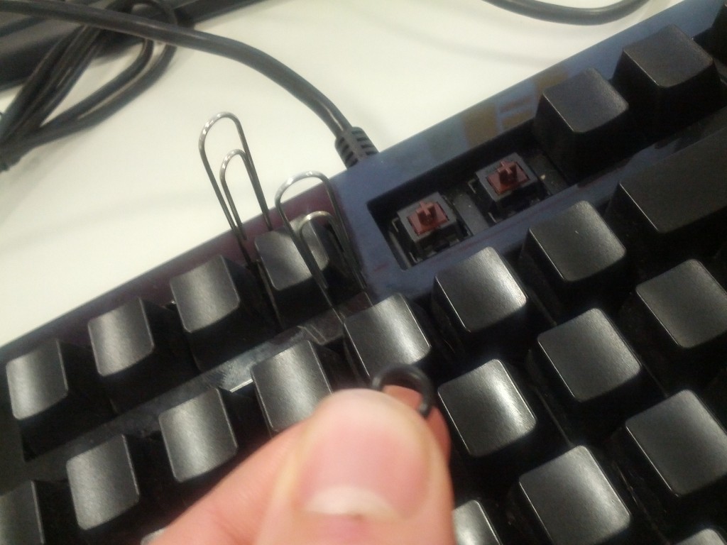
There’s a number of online stores happy to sell you the rings – although in my case, I just ordered the raw thing from Amazon than a keyboard shop. I also decided against spending the $10 for a keycap remover which was a good move –  a couple paperclips were effective enough.

OK keyboard, I know it's not quite the same, but it's time to put a rubber on it...

OK keyboard, I know it’s not quite the same, but it’s time to put a rubber on it…

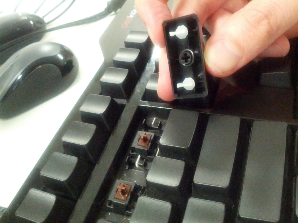
Generally the replacement was easy, the biggest issue was the spreader/stabiliser bar keys, such as the Enter, Backspace, Shift and Space keys – these ones have a little metal bar which you need to stretch apart to unhook the key from and to hook it back on once the rubber ring is installed.

The tricky keys - don't just pull them off, unless you want to break the white plastic loops.

The tricky keys – don’t just pull them off, unless you want to break the white plastic loops. You can see the little rubber ring I’ve just added to the keycap.

Next up is working to improve my typing accuracy – I can already thrash out some insanely fast stuff, but my accuracy rate can vary a lot (partially due to bad spelling), but sitting down and forcing myself to slow slightly for more accuracy would be a good trade off.

I’m also pondering learning a different layout like Dvorak which could be a good excuse to learn a new typing style and get some performance advantages.

Android via serial to Arduino

Whilst I’ve been pretty busy lately, I recently made another order from Mindkits and got to work with testing some of my ideas for my Arduino-based remote management solution for my home server.

There’s 4 major parts to this solution

  1. Connectivity to the computer’s serial port (a motherboard 10-pin header) and being able to communicate with the serial port using the Arduino.
  2. An Arduino controlled switch to turn the computer motherboard’s reset pins on and off.
  3. Connection into one of my old HTC Magic Android cellphones.
  4. Connection of 1-wire temperature sensors in key parts of the server’s case.

I’m using a stock standard Arduino Uno/Eleven for this project, for two main reasons:

  1. The HTC Magic phone is quite an old model of Android phones, effectively it’s the second generation after the original G1 and was the first officially available Android phone in New Zealand. Whilst I have loaded the last stable version of Cynogenmod released for it onto the phone, it’s only Android 2.2 and doesn’t feature the Android USB Accessory API support, so there was no point getting something like the USBDroid model.
  2. Rather than paying extra for ethernet connectivity, I’m planning to write an Android application that runs on the phone in the background that provides all the logic behind the remote management program for the server and connectivity via Wifi, 3G and SMS – I figure that the Android platform is better places for the management program anyway with a more sophisticated software

I purchased some protoshields for the Arduino, so my plan is to develop all my circuit logic as an addon shield so it will be possible to stack other shields on in future if I want to add some new applications/functionality to the system.

I’m new to the electronics, the Arduino coding AND the Android development requirements, so it’s an awesome learning curve project for me to start getting my head around all these technologies. :-)

The easiest bit to solve is the control of the computer’s reset header – I need this in order to be able to reboot a crashed system, something that has happened a couple of times due to flaky hardware.

To control the reset, I can use a simple transistor switched circuit, there’s a few resources around for novices to follow, I found this one useful. The only concerns I have is that I need to research and find out what the voltage on the reset headers is – I’m assuming 5V, but it could be anything from 3V to 12V….
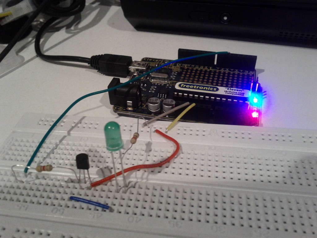
Tested the switch by using the Arduino to turn on the LED using a transistor.

The connectivity to the server seems pretty straightforwards – I’ll be using an RS232 shifter circuit (like this one) to connect the PC serial port to the Arduino, although I might end up re-implementing that circuit directly on the protoshield and using a 10-pin IEC connector to plug directly into the motherboard’s serial header

The phone will be connected using the debug serial port in the HTC Magic – it seems a number of the earlier HTC models can provide serial over some of the extra pins in the ExtUSB plug they use.

I’m not totally sure how I’ll be connecting both serial ports just yet – the Ardunio has one hardware UART onboard on pins 0 and 1, but I’m not sure if I can use those without losing the ability to manage the Arduino via it’s USB port – ideally I want the capability to still update the Arduino from the server it’s connected to.

It is possible to connect additional serial ports using software and there’s even a handy library for it, so I have that option for one or both ports. I’ll just have to code my software to be aware that the connection might be lossy or imperfect and to be patient and retry stuff.

I purchased an (expensive!) breakout board for the ExtUSB port which will make the soldering a *bit* easier, but considering the size of it, it still won’t be any walk in the park…
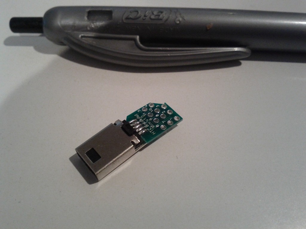
From uber-tiny to just plain tiny :-/

Fortunately since I’m using Cynogenmod, all the OS-side software is sorted and the kernel built with the correct parameters to enable the serial port functionality, providing me with a /dev/ttyMSM2 character device out-of-the-box.

Because I wanted to give it a go and see how the phone ran, I used some header pins to connect to the breakout board as they fit in the holes snugly – there must be some better tools available for connecting to PCBs and device legs without soldering for testing purposes, so I’ll need to do some more research for future.
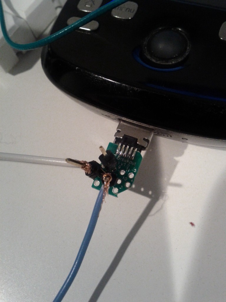
World’s dodgiest serial connection – also GND and TX pins connected only, it sends 2.8V into the Arduino which is OK, but I need to do a step down circuit before I can transmit from 5V back into the phone.
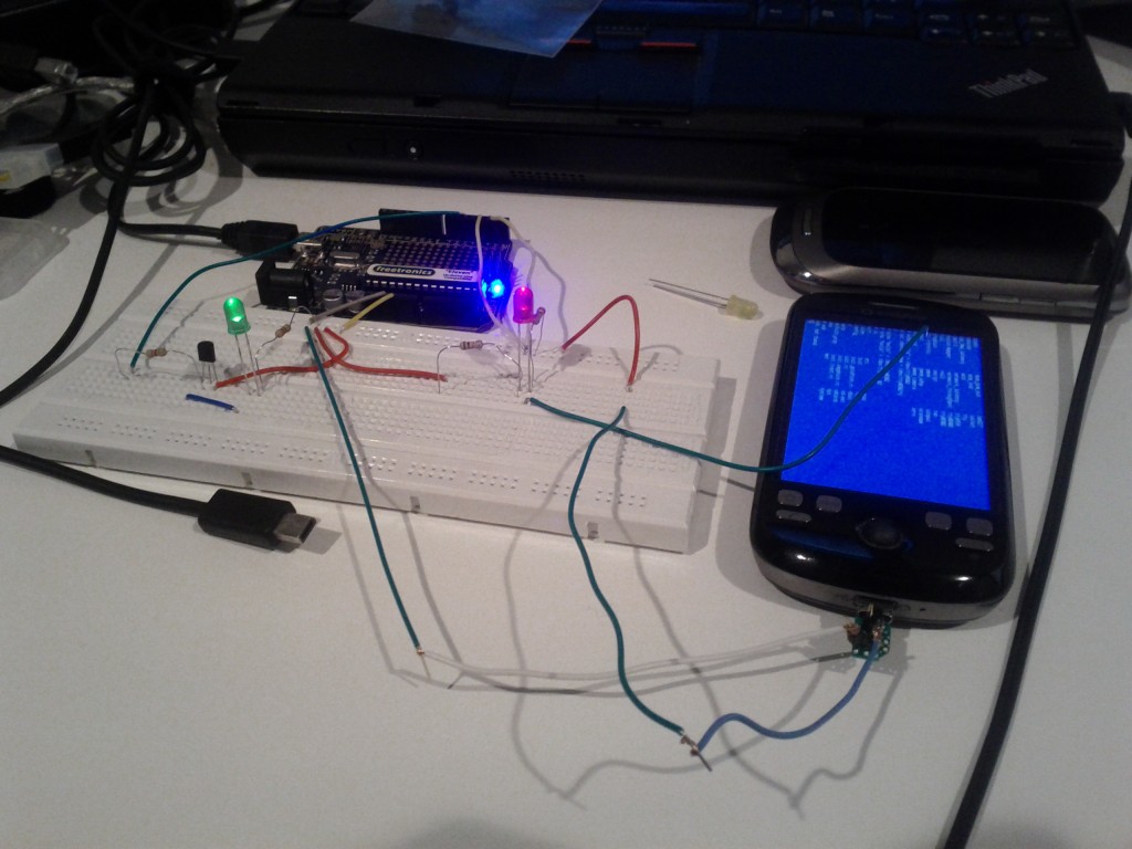
Hacky hacks
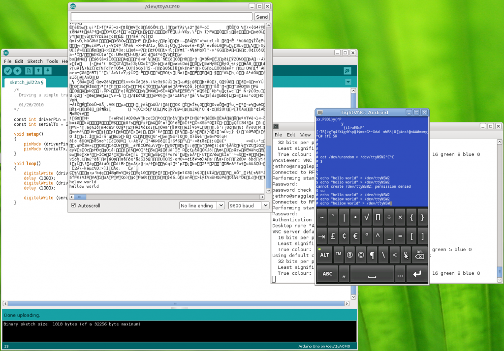
VNCd into the phone and sending messages over the serial line, which is connected to pin 1 (TX) on the Arduino, so the messages appear in the serial monitor

Based on these results it’s looking good – at least I’ve validated my understand of what is possible, so the next step is to turn some of this into a proper circuit.

My current plan is to do a short wire run from the ExtUSB connector breakout board into a small PCB which will split the output into the 3 wires for serial (RX, TX, Ground) and also take the 4 wires for USB and connect them to a USB port, so that I can plugin a USB cable to charge and manage the phone. From there, I can run the 3 serial wires to a header on the protoshield I’m building to connect into the Arduino.

I’ll have to work out how the Android phone and the Arduino will communicate for the management functionality, at this stage I’m planning to have an app that would send specific commands to the Arduino via serial and maybe the ability to get the output from the server’s serial port via the serial link to the Android phone by encapsulating the data or some other behavior.

Next steps is to get a better soldering iron so hopefully will be able to do the initial soldering I need for the HTC magic serial connection next weekend. :-)


Lenovo & tp-fan fun

I quite like my Lenovo X201i laptop, I’ve been using it for a couple years now and it’s turned out to be the ideal combination of size and usability – the 12″ form factor means I can carry it around easily enough, it has plenty of performance (particularly since I upgraded it to an SSD and 8GB of RAM) and I can see myself using it for the foreseeable future.

Unfortunately it does have a few issues… the crappy “Thinkpad Wireless” default card that comes in it caused me no end of headaches and the BIOS has always been a

Thankfully most of the major BIOS flaws have been resolved in part due to subsequent updates, but also thanks to the efforts of the Linux kernel developers to work around weird bits of the BIOS’s behavior.

Sadly not all issues have been resolved, in particular, the thermal management is still flawed and fails to adequately handle the maximum heat output of the laptop. I recently discovered that when you’re unfortunate enough to run some very CPU intensive single-threaded processes, by keeping 1/4 cores at 100% for an extended period of time the Lenovo laptop will overheat and issue an emergency thermal shutdown to the OS.

During this time the fan increases in speed, but still has quite a low noise level and airflow volume, which is very hot to the touch, it appears the issue is due to the Lenovo BIOS not ramping the fan speed up high enough to meet the heat being produced.

Thanks to the excellent Thinkwiki site, there’s detailed information on how you can force specific fan speeds using the thinkpad_acpi kernel module, as well as details on various scripts and fan control solutions people have written.

What’s interesting is that when running the fan on level 7 (the maximum speed), the fan still doesn’t spin particularly fast or loudly, no more than when the overheating occurs. But reading the wiki shows that there is a “disengaged” mode, where the fan will run at the true maximum system speed.

It appears to me that the BIOS has the 100% speed setting for the fan set at too low a threshold, the smart fix would be to correct the BIOS so that 100% is actually the true maximum speed of the fan and to scale up slowly to keep the CPU at a reasonable temperature.

In order to fix it for myself, I obtained the tp-fan program, which runs a python daemon to monitor and adjust the fan speeds in the system based on the configured options. Sadly it’s not able to scale between “100%” and “disengaged” speeds, meaning I have the choice of quiet running or loud running but no middle ground.

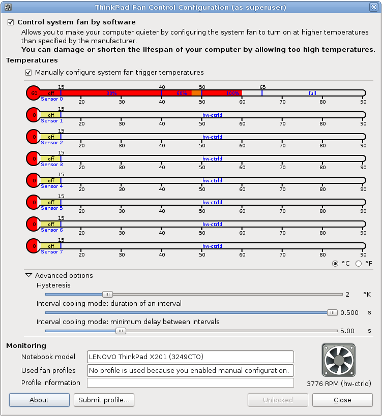
Thanks to tpfan’s UI, I was able to tweak the speed positions until I obtained the right balance, the fans will now run at up to 100% for all normal tasks, often sitting just under 50 degrees at 60% fan speed.

When running a highly CPU intensive task, the fan will jump up to the max speed and run at that until the temperature drops sufficiently.  In practice it’s worked pretty well, I don’t get too much jumping up and down of the fan speed and my system hasn’t had any thermal shutdowns since I started using it.

Whilst it’s clearly a fault with the Lenovo BIOS not handling the fans properly, it raised a few other questions for me:

  • Why does the OS lack logic to move CPU intensive tasks between cores? Shuffling high intensive loads between idle cores would reduce the heat and require less active cooling by the system fans – even on a working system that won’t overheat, this would be a good way to reduce power consumption.
  • Why doesn’t the OS have a feature to throttle the CPU clock speed down as the CPU temperature rises? It would be better than having the all or nothing approach that it currently enforces, better to have a slower computer than a fried computer.

Clearly I need some more free time to start writing kernel patches for my laptop, although I fear what new dangerous geeky paths this might lead me into. :-/