Tag Archives: Electronics

HowAlarming

The previous owners of our house had left us with a reasonably comprehensive alarm system wired throughout the house, however like many alarm systems currently in homes, it required an analogue phone line to be able to call back to any kind of monitoring service.

To upgrade the alarm to an IP module via the monitoring company would be at least $500 in parts and seemed to consist of hooking the phone line to essentially a VoIP ATA adaptor which can phone home to their service.

As a home owner I want it internet connected so I can do self-monitoring, give me the ability to control remotely and to integrate it with IP-based camera systems. Most of the conventional alarm companies seem to offer none of things, or only very expensive sub-standard solutions.

To make things worse, their monitoring services are also pretty poor. Most of the companies I spoke to would receive an alarm, then call me to tell me about it/check with me and only then send someone out to investigate. The existing alarm company the previous owner was using didn’t even offer a callout security service!

Spark (NZ incumbent telco) recently brought out a consumer product called Morepork (as seen on stuff!) which looks attractive for your average non-techie consumer, but I’m not particularly keen to tie myself to Spark’s platform and it is very expensive, especially when considering I have to discard an existing functional system and start from scratch. There’s also some design weaknesses like the cameras being mains dependent, which I don’t consider acceptable given how easy it is to cut power to a house.

So I decided that I’d like to get my existing alarm IP connected, but importantly, I wanted to retain complete control over the process of generating an alert and delivering it to my phone so that it’s as fast as possible and also, as reliable as possible.

Not only did I want to avoid the human factor, but I’m also wary of the proprietary technologies used by most of the alarm companies off-the-shelf solutions. I have some strong doubts about the security of a number of offers, not to mention life span (oh sorry that alarm is EOL, no new mobile app for you) and the level of customisation/integration offered (oh you want to link your alarm with your camera motion detection? Sorry, we don’t support that).


I did some research on my alarm system and found it’s one of the DSC PowerSeries range which is a large Canadian company operating globally. The good thing about them being a large global player is that there’s a heap of reference material about their products online.

With a quick search I was able to find user guides, installer guides, programming guides and more. They also include a full wiring diagram inside the alarm control centre which is exceptionally useful, since it essentially explains how you can connect any kind of sensors yourself which can save a whole heap of money compared to paying for an alarm company to do the installation.

Spagettie

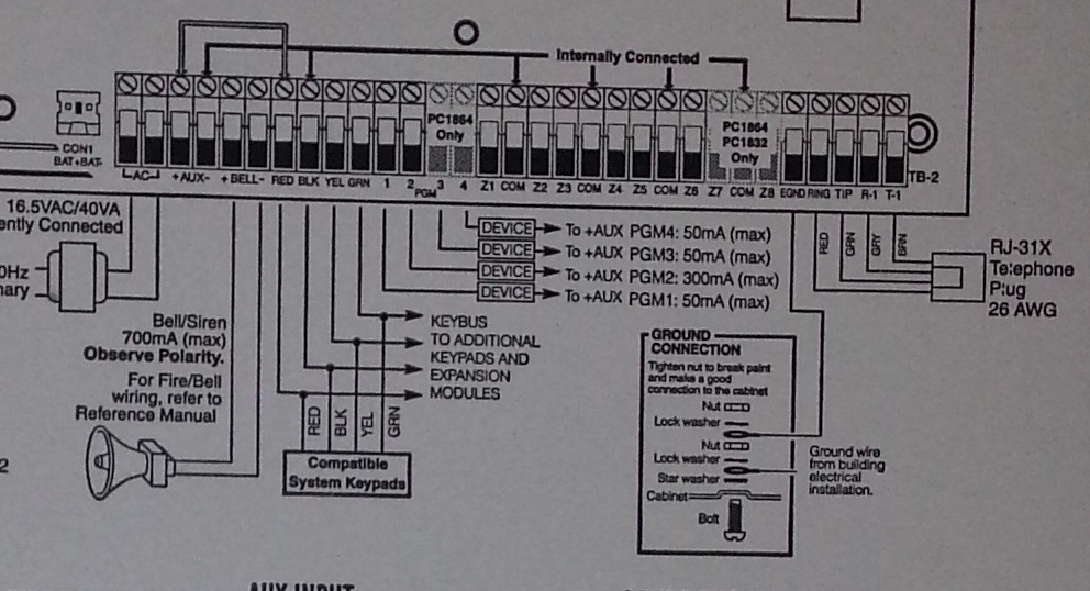
I wish all my electronic devices came with documentation this detailed.

The other great thing about this alarm is that since DSC is so massive, there’s an ecosystem of third party vendors offering components for it. Searching for third party IP modules, I ran into this article where the author purchased an IP module from a company known as Envisalink and used it’s third party API to write custom code to get alarm events and issue commands.

A third party API sounded perfect, so I purchased the EnvisaLink EVL-4 for $239 NZD delivered and did the installation myself. In theory the installation is easy, just a case of powering down the alarm (not touching any 240V hard wired mains in the process) and connecting it via the 4 wire keypad bus.

In my case it ended up being a bit more complex since the previous owner had helpfully never given me any of the master/installer alarm codes, so I ended up doing a factory reset of the unit and re-programming it from scratch (which means all the sensors, etc) which takes about a day to figure out and do the first time. The plus side is that this gave me complete control over the unit and I was able to do things like deprogram the old alarm company’s phone number to stop repeat failed callout attempts.

Once connected, the EnvisaLink unit was remarkably hassle free to setup – it grabbed a DHCP lease, connected to the internet and phoned home to the vendor’s free monitoring service.

Installed with pretty LEDs!

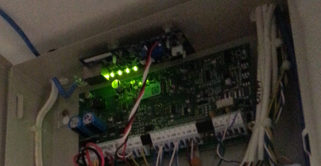
EnvisaLink unit installed at the top above the alarm control circuit. A++ for LED ricing guys!


The EnvisaLink hardware is a great little unit and the third party programmer’s interface is reasonably well documented and works without too much grief. Unfortunately the rest of the experience of the company selling it isn’t particularly good. Specifically:

  • Their website places the order by emailing their accounts mailbox. How do I know? Because they printed the email including my credit card number in full and sent it as the packing slip on it’s journey across the world. Great PCI compliance guys!
  • They show the product as working with Android, iPhone and Blackberry. They carefully avoid saying it has native apps, they actually mean it has a “smart phone” optimized version, which is as terrible as it sounds.
  • I can’t enable alerts on their service since their signup process keeps sending my email a blank validation code. So I had an alarm that couldn’t alarm me via their service.
  • No 2FA on logging into the alarm website, so you could brute force login and then disable the alarm remotely… or set it off if you just want to annoy the occupants.

I haven’t dug into the communications between the unit and it’s vendor, I sure hope it’s SSL/TLS secured and doesn’t have the ability to remotely exploit it and upgrade it, but I’m not going to chance it. Even if they’ve properly encrypted and secured comms between the unit and their servers, the security is limited to the best practices of the company and software which already look disturbingly weak.

Thankfully my requirements for the module is purely it’s third party API so I can integrate with my own systems, so I can ignore all these issues and put it on it’s own little isolated VLAN where it can’t cause any trouble and talk to anything but my server.


So having sorted out the hardware and gotten the alarm onto the network, I now needed some software that would at least meet the basic alerting requirements I have.

There’s an existing comprehensive Java/Android-based product (plainly labeled as “DSC Security Server”) which looks very configurable, but I specifically wanted something open source to make sure the alarm integration remained maintainable long term and to use Google Push Notifications  for instant alerting on both Android (which supports long running background processes) and iOS (which does not – hence you must use push notifications via APNS).

I ended up taking advantage of some existing public code for handling the various commands and error responses from the Envisalink/DSC alarm combination but reworked it a bit so I now have a module system that consists of “alarm integrators” exchanging information/events with the alarm system and “alarm consumers” which decide what to do with the events generated. These all communicate via a simple beanstalk queue.

This design gives ultimate simplicity – each program is not much more than a small script and there’s a standard documented format for anyone whom wants to add support for other alarm integrators or alarm consumers in future. I wanted it kept simple, making it the sort of thing you could dump onto a Raspberry Pi and have anyone with basic scripting skills be able to debug and adjust it.

I’ve assembled these programs into an open source package I’m calling “HowAlarming”“, hopefully it might be useful for anyone in future with the same alarm system or wanting a foundation for building their own software for other alarms (or even their own alarms).


The simplest solution to get alerts from the system would be by sending SMS using one of the many different web-based SMS services, but I wanted something I can extend to support receiving images from the surveillance system in future and maybe also sending commands back.

Hence I’ve written a companion Android app which receives messages from HowAlarming via push notifications and maintains an event log and the current state of the alarm.

UX doens't get much better than this.

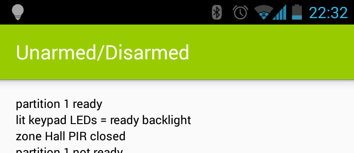
UX doens’t get much better than this.

It’s pretty basic, but it offers the MVP that I require. Took about a day to hack together not having done any Android or Java before, thankfully Android Studio makes the process pretty easy with lots of hand holding and easy integration with the simulators and native devices.

TBD if I can hack something together in a day not having done any native app development before that’s better than many of the offerings from the alarm companies currently around, they need to be asking themselves some hard questions. At the very least, they should get someone to write some apps that can pull their customer’s alarm state from their current phone-home infrastructure – there’s probably good money to be made giving existing customers on non-IP era alarms upgrades given the number of installations out there.


So far my solution is working well for me. It’s not without it’s potential problems, for example alarm communications are now at the mercy of a power/internet outage whereas previously as long as the phone line was intact, it could call out. However this is easily fixed with my UPS and 3G failover modem – the 3G actually makes it better than previously.


The other potential issue is that I don’t know what insurance would classify this nature of self-monitoring as. I have mine declared as “un-monitored” to avoid any complications, but if your insurance conditions require monitoring I’m unsure if a home-grown solution would meet those requirements (even if it is better than 90% of the alarm companies). So do your research and check your contracts & terms.

Amberdms Billing System 2.0.0

It’s been a long while since my last release of the Amberdms Billing System (ABS), but at last I’ve finished merging in and testing all the new features that were worked on during my time running Amberdms with two other great coders and prepared a new stable release and documentation.

If you’re not familiar with ABS, it’s an open source billing system providing double-entry accounting, invoicing (with PDF generation), customer management, service billing (including telco usage billing) and time sheeting and billing functionality.

It’s been used by a couple smaller ISPs in New Zealand as well as various open source users around the world and is extremely flexible and powerful software (in my biased opinion). :-)

Accounting and billing isn't a sexy application... but it needs to get done.

Accounting and billing isn’t a sexy application… but it needs to get done.

The major developments of this release include:

  • New invoice templates using HTML/CSS with Webkit as a rendering engine to produce stunning PDF invoices.
  • Numerous improvements and additions to the customer management page.
  • Credit notes & customer credit balance management.
  • Easier bulk handling of payments with bulk payment interface and (beta) bank statement import function.
  • Support for VoIP billing, including charging customers for all calls made based on a configurable call record database as the source.
  • Service bundling to group multiple services together to form packages.

If you’re running a business, particularly a service or technology orientated company, I invite you to take a look and check out ABS. Even if you’re using an existing accounting system like Xero, ABS is a great fit for the billing requirements and is a great base to use, rather than building your own in house billing platform.

You can read the release announcement details here, or go directly to the open source project page and download the installation guides and source code.

RS232 Shifter Board

As part of my project to make an Arduino based watchdog for my home server, I went and picked up a proper soldering iron today and assembled the RS232 Shifter Circuit I had purchased from Sparkfun/Mindkits.

I ended up getting a Goot soldering iron – it wasn’t too cheap, but the reviews I was reading online suggested it was the next best thing to a proper soldering station and a quality Japanese tool. It’s also 46W, so much better for the lead-free solder I’m using, compared to the crappy 15W DSE brand generic iron I was using previously.

Tool of the gods.

It made a massive difference to the soldering efforts, the lead-free solder melted without issue and flowed smoothly – plus the fine point conical tip made getting the solder into key areas a lot easier.

The tips are changeable and I’ve been advised by an electronics fixing friend to get a set of tip types, as certain ones suit different tasks better than others.

Whilst the new soldering iron is a huge improvement, my soldering skill is still a bit poor, I had a few text-book joins where the solder flowed perfectly and bonded with a smooth shiny surface, but a lot of my joins tend to be slightly one sided, where the solder hasn’t flowed right around the components lead and PCB hole which makes then a bit weak.

I’m also tending to leave too much solder on the component lead, which leaves larger joins than really needed, so need to work on how much solder I apply.

Parents, avert your children’s eyes from this soldering monstrosity!

On the flip side, the top looks great ;-)

After constructing the circuit, I gave it a test by connecting the TX and RX of the shifter circuit to the TX and RX on the Arduino, which basically uses the Arduino as an UART to RS232(over USB) adapter.

Then I connected the new DB9 port to my laptop and typed messages into the Arduino serial monitor, to have them passed through my new circuit and into my laptop’s DB9 port.

Amazingly, things worked first time and I’m able to successfully receive data via the shifter board – in my quick test TX from the shifter board wasn’t working, but it may have been a serial speed/config issue that I just need to tweak in the OS, rather than the board itself.

Arduino IDE to Minicom via an Arduino, my new shifter circuit and my laptop’s USB to RS232 adapter.

The next step is connecting this shifter circuit to the digital I/O ports on the Arduino and using the software serial library to add a second serial port to the device. I can then do the same to the HTC Magic serial break out and I’ll basically have an Arduno with 3 serial ports in total –  the onboard UART, the DB9 PC via shifter and the HTC magic.

Once that’s done, it’s just a case of writing the software needed to turn the collection of hacks into a hardware watchdog and serial remote access system. :-)

And once that’s all working, I’ll build a final solution using one of the Arduino prototyping shields from Freetronics, which will include all the shifter circuitry onboard and just provide a 2×5 IEC pin header to plug a ribbon cable directly into the server’s motherboard serial port header.

Android via serial to Arduino

Whilst I’ve been pretty busy lately, I recently made another order from Mindkits and got to work with testing some of my ideas for my Arduino-based remote management solution for my home server.

There’s 4 major parts to this solution

  1. Connectivity to the computer’s serial port (a motherboard 10-pin header) and being able to communicate with the serial port using the Arduino.
  2. An Arduino controlled switch to turn the computer motherboard’s reset pins on and off.
  3. Connection into one of my old HTC Magic Android cellphones.
  4. Connection of 1-wire temperature sensors in key parts of the server’s case.

I’m using a stock standard Arduino Uno/Eleven for this project, for two main reasons:

  1. The HTC Magic phone is quite an old model of Android phones, effectively it’s the second generation after the original G1 and was the first officially available Android phone in New Zealand. Whilst I have loaded the last stable version of Cynogenmod released for it onto the phone, it’s only Android 2.2 and doesn’t feature the Android USB Accessory API support, so there was no point getting something like the USBDroid model.
  2. Rather than paying extra for ethernet connectivity, I’m planning to write an Android application that runs on the phone in the background that provides all the logic behind the remote management program for the server and connectivity via Wifi, 3G and SMS – I figure that the Android platform is better places for the management program anyway with a more sophisticated software

I purchased some protoshields for the Arduino, so my plan is to develop all my circuit logic as an addon shield so it will be possible to stack other shields on in future if I want to add some new applications/functionality to the system.

I’m new to the electronics, the Arduino coding AND the Android development requirements, so it’s an awesome learning curve project for me to start getting my head around all these technologies. :-)

The easiest bit to solve is the control of the computer’s reset header – I need this in order to be able to reboot a crashed system, something that has happened a couple of times due to flaky hardware.

To control the reset, I can use a simple transistor switched circuit, there’s a few resources around for novices to follow, I found this one useful. The only concerns I have is that I need to research and find out what the voltage on the reset headers is – I’m assuming 5V, but it could be anything from 3V to 12V….

Tested the switch by using the Arduino to turn on the LED using a transistor.

The connectivity to the server seems pretty straightforwards – I’ll be using an RS232 shifter circuit (like this one) to connect the PC serial port to the Arduino, although I might end up re-implementing that circuit directly on the protoshield and using a 10-pin IEC connector to plug directly into the motherboard’s serial header

The phone will be connected using the debug serial port in the HTC Magic – it seems a number of the earlier HTC models can provide serial over some of the extra pins in the ExtUSB plug they use.

I’m not totally sure how I’ll be connecting both serial ports just yet – the Ardunio has one hardware UART onboard on pins 0 and 1, but I’m not sure if I can use those without losing the ability to manage the Arduino via it’s USB port – ideally I want the capability to still update the Arduino from the server it’s connected to.

It is possible to connect additional serial ports using software and there’s even a handy library for it, so I have that option for one or both ports. I’ll just have to code my software to be aware that the connection might be lossy or imperfect and to be patient and retry stuff.

I purchased an (expensive!) breakout board for the ExtUSB port which will make the soldering a *bit* easier, but considering the size of it, it still won’t be any walk in the park…

From uber-tiny to just plain tiny :-/

Fortunately since I’m using Cynogenmod, all the OS-side software is sorted and the kernel built with the correct parameters to enable the serial port functionality, providing me with a /dev/ttyMSM2 character device out-of-the-box.

Because I wanted to give it a go and see how the phone ran, I used some header pins to connect to the breakout board as they fit in the holes snugly – there must be some better tools available for connecting to PCBs and device legs without soldering for testing purposes, so I’ll need to do some more research for future.

World’s dodgiest serial connection – also GND and TX pins connected only, it sends 2.8V into the Arduino which is OK, but I need to do a step down circuit before I can transmit from 5V back into the phone.

Hacky hacks

VNCd into the phone and sending messages over the serial line, which is connected to pin 1 (TX) on the Arduino, so the messages appear in the serial monitor

Based on these results it’s looking good – at least I’ve validated my understand of what is possible, so the next step is to turn some of this into a proper circuit.

My current plan is to do a short wire run from the ExtUSB connector breakout board into a small PCB which will split the output into the 3 wires for serial (RX, TX, Ground) and also take the 4 wires for USB and connect them to a USB port, so that I can plugin a USB cable to charge and manage the phone. From there, I can run the 3 serial wires to a header on the protoshield I’m building to connect into the Arduino.

I’ll have to work out how the Android phone and the Arduino will communicate for the management functionality, at this stage I’m planning to have an app that would send specific commands to the Arduino via serial and maybe the ability to get the output from the server’s serial port via the serial link to the Android phone by encapsulating the data or some other behavior.

Next steps is to get a better soldering iron so hopefully will be able to do the initial soldering I need for the HTC magic serial connection next weekend. :-)

Soldering Adventures

As part of my efforts to learn more about electronics, I recently obtained a power supply kit that breaks the standard 5V USB output into 3.3V and 5V bread-board connectable outputs from Mindkits (who resell Sparkfun kits in NZ, amongst other stuff).

I went for a USB-powered model rather than a typical round-pin DC supply, since I have an abundance of USB power sources with me all the time (both laptop and wall adaptors) and it’s much better than having yet another damn power brick hanging around.

I finally managed to get around to making the time to try it out this weekend and dug out the soldering iron to tackle the challenge – past soldering exploits have never fared particularly well, but I figure sooner or later I’ll learn something and make a working device. ;-)

How hard could this possibly be? :-P

One of the biggest challenges I found was actually holding such a small PCB still, whilst trying to align solder and the iron – think one of my next purchases will be some sort of clamp to hold the board in place.

I’m not convinced that my soldering iron is particularly good either, need to do some research on the best type of soldering head (round vs chisel?). I’d probably go better with more gun shaped soldering iron than the round pencil design, I just tend to find it easier to align.

Ready, set, solder!

I started off doing the small components like resisters and small caps, before moving on to the voltage regular, switch, USB port and pin headers.

Apologies to any electrical engineers or skilled hobbyist reading this blog, but my soldering is pretty terrible, as you can see. Take note that this is the first thing I’ve soldered that actually works :-P

Oh god, oh god my eyes!

I started with the resisters in the middle, as you can see my soldering was pretty terrible there – used too much solder and ended up making large messy blobs.

Later I got better at briefly heating the legs and then applying the solder in a way that allowed it to run down and bond with the PCB, so my later joins got a lot better, eg the USB socket with it’s 4 close small pins.

I got an impromptu lesson to using a multimeter as the circuit wouldn’t work initially – I had managed to make a PSU that was always on (ignoring the switch status) and provided no 3.3V output.

Thanks to the simplicity of this kit, it was pretty easy to test each component to figure out where my bad joins were and I re-soldered a few of the bad earlier joins.

The only real headache was the voltage regulator – for some reason I had real difficulty getting the solder to bond with the middle pin and the PCB and had to redo it several times – it’s still not perfect TBH :-(

Assembled :-D

Shiny shiny! (OMG, an artsy picture without using Instagram!)

So far the kit seems pretty good, it was really easy to assemble with the clear silkscreen markings – most work I had to do was lookup the resister code/colors, which is trivial thanks to Electrodroid on my phone. :-)

The one design issue I do have with the kit, is that the positioning of the breadboard connectors requires you to break the header pins into single units, but doing this really weakens the design, since it’s just one tiny solder joint holding the pin to the PCB – I do fear the force of inserting and removing from breadboards will wear it down a bit over time.

To counter this a bit, I’ve stuck a blob of hot glue around the headers, to give them a bit more integrity – although the 3.3V pin soldering joint is playing up and might need redoing anyway.

Hot glue solves all! (also stuck some around the voltage regulator as one of the solder joints isn't that great, but I can't fix it without risking ruining the PCB trace)

Looking at the round-DC connector version of the kit, the design instead has two pairs of 2x pin headers, which I suspect will make it a bit more sturdy.

Overall whilst it’s a painful learning curve trying to get the soldering right, I didn’t burn myself *too* badly and whilst not a shining example of art, the board works and powers up.

Next time, I’ll be tackling the RS232 shifter kit and then working to hook up an RS232 power to an Arduino’s digital pins using a software serial driver. And after that, I might have a go at making some temperature sensor 1-wire boards to install around my server case using the small square prototyping boards I brought.

Hopefully by then my soldering will be an acceptable level. :-)

Next kit to make - the RS232 shifter, with lots of lovely close resisters to solder.

Leosticks are a gateway drug

At linux.conf.au earlier this year, the guys behind Freetronics gave every attendee a free Leostick Arduino compatible board.

As I predicted at the time, this quickly became the gateway drug – having been given an awesome 8-bit processor that can run off the USB port and can provide any possibility of input/output with both digital and analogue hardware, it was inevitable that I would want to actually acquire some hardware to connect to it!

Beware kids, this is what crack looks like.

My background into actual electronics hasn’t been great, my parents kindly got me a Dick Smith starter kit when I was much younger (remember back in the day when DSE actually sold components! Now I feel old :-/) but I never quite managed to grasp all the concepts and a few attempts since then haven’t been that successful.

Part of the issue for me is I learn by doing and having good resources to refer to, back then it wasn’t so easy, however with internet connectivity and thousands of companies selling components to consumers offering tutorials and circuit design information, it’s never been easier.

Interestingly I found it hard to get a real good “you’re a complete novice with no clue about any of this” guide, but the Arduino learning resources are very good at detailing how their digital circuits work and with a bit of wikipediaing, got me on the right track so far.

Also not having the right tools and components for the job is an issue, so I made a decision to get a proper range of components, tools, hookup wire and some Arduino units to make a few fun projects to learn how to make this stuff work.

I settled on 3 main projects:

  1. Temperature monitoring inside my home server – this is a whitebox machine so doesn’t have too many sensors in good locations, I’d like to be able to monitor some of the major disk bays, fans, motherboard, etc.
  2. Out-of-band serial management and watchdog restart of my home server. This is more complex & ambitious, but all the components are there – with a RS232 to TTY conversion circuit I can read the server’s serial port from the Arduino and use the Arduno and a transistor to control the reset header on the motherboard to power-restart if my slightly flaky CPU crashes again.
  3. Android controlled projects. This is a great one, since I have an abundance of older model Android phones available and would like a project that allows me to improve my C coding (Arduino) and to learn Java/Dalvik (Android). This ticks both boxes. ATM considering adding an Android phone to the Arduino server monitoring solution, or maybe hooking it into my car and using the Android phone as the display.

These cover a few main areas – to learn how to talk with one wire sensor devices, to earn how to use transistors to act as switches, to learn different forms of serial communication and to learn some new programming languages.

Having next to no current electronic parts (soldering iron, breadboard and my general PC tools were about it) I went down the path of ordering a full set of different bits to make sure I had a good selection of tools and parts to make most circuits I want.

Ended up sourcing most of my electronic components (resister packs, prototyping boards, hookup wire, general capacitors & ICs) from Mindkits in NZ, who also import a lot of Sparkfun stuff giving them a pretty awesome range.

Whilst the Arduinos I ordered supply 5V and 3.3V, I grabbed a separate USB-powered supply kit for projects needing their own feed – much easier running off USB (of which I have an abundance of ports around) than adding yet-another-wallwart transformer. I haven’t tackled it yet, but I’m sure my soldering skills will be horrific and naturally worth blogging about in future to scare any competent electronics geek.

I also grabbed two Dallas 1-wire temperature sensors, which whilst expensive compared to the analog options are so damn simple to work with and can be daisy chained. Freetronics sell a breakout board model all pre-assembled, but they’re pricey and they’re so simple you can just wire the sensors straight back to your Arduino circuit anyway.

Next I decided to order some regular size Arduinos from Freetronics – if I start wanting to make my own shields (expansion boards for the Arduinos), I’d need a regular sized unit rather than the ultrasmall Leostick.

Ended up getting the classic Arduino Eleven/Uno and one of the Arduino USB Droids which provide a USB Host port so they can be used with Android phones to write software than can interface with hardware.

After a bit of time, all my bits have arrived from AU and the US and now I’m already to go – planning to blog my progress as I get on with my electronics discovery – hopefully before long I’ll have some neat circuit designs up on here. :-)

Once I actually have a clue what I’m doing, I’ll probably go and prepare a useful resource on learning from scratch, to cover all the gaps that I found hard to fill, since learning this stuff opens up so many exciting projects once you get past the initial barrier.

Arduino Uno/Eleven making an LED blink. HIGH TECH STUFF ;-)

Push a button to make the LED blink! Sure you can do this with just a battery, switch and LED, but using a whole CPU to read the button state and switch on the LED is much geekier! ;-)

1-wire temperature sensors. Notably with a few more than one wire. ;-)

I’ll keep posting my adventures as I get further into the development of different designs, I expect this is going to become a fun new hobby that ties into my other two main interests – computers and things with blinky lights. :-)