Tag Archives: networking

FailberryPi – Diverse carrier links for your home data center

Given the amount of internet connected things I now rely on at home, I’ve been considering redundant internet links for a while. And thanks to the affordability of 3G/4G connectivity, it’s easier than ever to have a completely diverse carrier at extremely low cost.

I’m using 2degrees which has a data SIM sharing service that allows me to have up to 5 other devices sharing the one data plan, so it literally costs me nothing to have the additional connection available 24×7.

My requirements were to:

  1. Handle the loss of the wired internet connection.
  2. Ensure that I can always VPN into the house network.
  3. Ensure that the security cameras can always upload footage to AWS S3.
  4. Ensure that the IoT house alarm can always dispatch events and alerts.

I ended up building three distinct components to build a failover solution that supports flipping between my wired (VDSL) and wireless (3G) connection:

  1. A small embedded GNU/Linux system that can bridge a USB 3G modem and an ethernet connection, with smarts to recover from various faults (like crashed 3G stick).
  2. A dynamic DNS solution, since my mobile telco certainly isn’t going to give me a static IP address, but I need inbound traffic.
  3. A DNS failover solution so I can redirect inbound requests (eg home VPN) to the currently active endpoint automatically when a failure has occurred.


The Hardware

I considered using a Mikrotik with USB for the 3G link – it is a supported feature, but I decided to avoid this route since I would need to replace my perfectly fine router for one with a USB port, plus I know from experience that USB 3G modems are fickle beasts that would be likely to need some scripting to workaround various issues.

For the same reason I excluded some 3G/4G router products available that take a USB modem and then provide ethernet or WiFi. I’m very dubious about how fault tolerant these products are (or how secure if consumer routers are anything to go by).

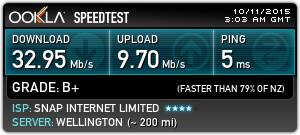
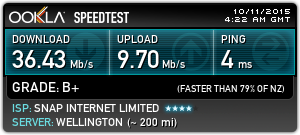
I started off the project using a very old embedded GNU/Linux board and 3G USB modem I had in the spare parts box, but unfortunately whilst I did eventually recycle this hardware into a working setup, the old embedded hardware had a very poor USB controller and was throttling my 3G connection to around 512kbps. :-(

Initial approach – Not a bomb, actually an ancient Gumstix Verdex with 3G modem.

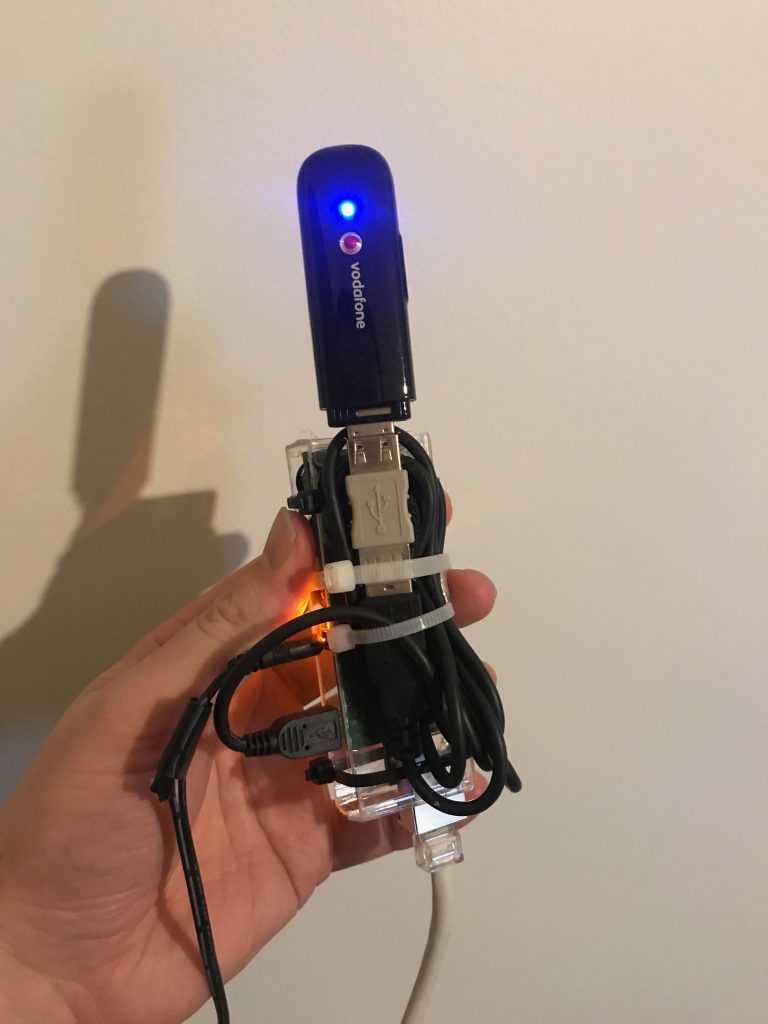
So I started again, this time using the very popular Raspberry Pi 2B hardware as the base for my setup. This is actually the first time I’ve played with a Raspberry Pi and I actually really enjoyed the experience.

The requirements for the router are extremely low – move packets between two interfaces, dial a modem and run some scripts. It actually feels wasteful using a whole Raspberry Pi with it’s whole 1GB of RAM and Quad Core ARM CPU, but they’re so accessible and cost affordable, it’s not worth the time messing around with any more obscure embedded boards.
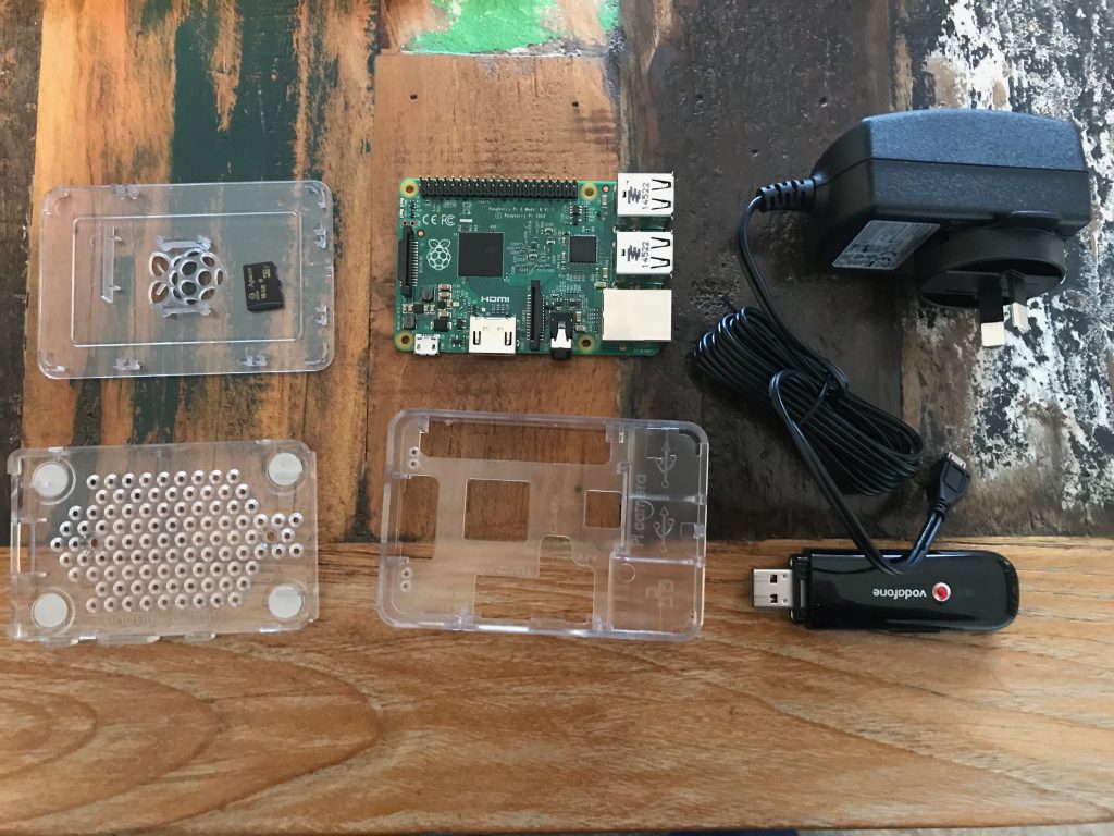
Pie ingredients

It took me all of 5 mins to assemble and boot an OS on this thing and have a full Debian install ready for work. For this speed and convenience I’ll happily pay a small price premium for the Raspberry Pi than some other random embedded vendors with much more painful install and upgrade processes.
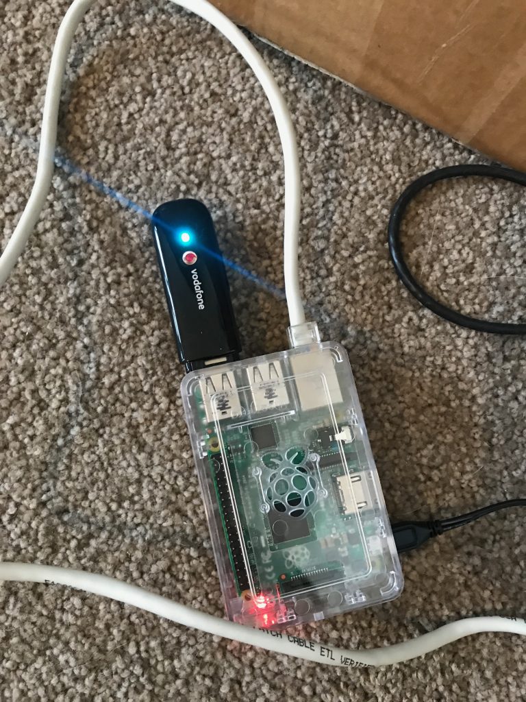
Baked!

It’s important to get a good power supply – 3G/4G modems tend to consume the full 500mW available to them. I kept getting under voltage warnings (the red light on the Pi turns off) with a 2.1 Amp phone charger I was using. Ended up buying the official 2.5 Amp Raspberry Pi charger, which powers the Raspberry Pi 2 + the 3G modem perfectly.

I brought the smallest (& cheapest) class 10 Micro SDHC card possible – 16GB. Of course this is way more than you actually need for a router, 4GB would have been plenty.

The ZTE MF180 USB 3G modem I used is a tricky beast on Linux, thanks to the kernel seeing it as a SCSI CDROM drive initially which masks the USB modem features. Whilst Linux has usb_modeswitch shipping as standard these days, I decided to completely disable the SCSI CDROM feature as per this blog post to avoid the issue entirely.


The Software

The Raspberry Pi I was given (thanks Calcinite! ?) had a faulty GPU so the HDMI didn’t work. Fortunately Raspberry Pi doesn’t let such a small issue like no display hold it back – it’s trivial to flash an image to the SD card from another machine and boot a headless installation.

  1. Download Raspbian minimal/lite (Debian + Raspberry Pi goodness).
  2. Installed image to the SD card using the very awesome Etcher.io (think “safe dd” for noobs) as per the install instructions using my iMac.
  3. Enable SSH as per instructions: “SSH can be enabled by placing a file named ssh, without any extension, onto the boot partition of the SD card. When the Pi boots, it looks for the ssh file. If it is found, SSH is enabled, and the file is deleted. The content of the file does not matter: it could contain text, or nothing at all.”
  4. Login with username “pi” and password “raspberry”.
  5. Change the password immediately before you put it online!
  6. Upgrade the Pi and enable automated updates in future with:
    apt-get update && apt-get -y upgrade
    apt-get install -y unattended-upgrades

The rest is somewhat specific to your setup, but my process was roughly:

  1. Install apps needed – wvdial for establishing the 3G connection via AT commands + PPP, iptables-persistent for firewalling, libusb-dev for building hub-ctrl and jq for parsing JSON responses.
    apt-get install -y wvdial iptables-persistent libusb-dev jq
  2. Configure a firewall. This is very specific to your network, but you’ll want both ipv4 and ipv6 rules in /etc/iptables/rules.* Generally you’d want something like:
    1. Masquerade (NAT) traffic going out of the ppp+ and eth0 interfaces.
    2. Permit forwarding traffic between the interfaces.
    3. Permit traffic in on port 9000 for the health check server.
  3. Enable IP forwarding (net.ipv4.ip_forward=1) in /etc/sysctl.conf.
  4. Build hub-ctrl. This utility allows the power cycling of the USB controller + attached devices in the Raspberry Pi, which is extremely useful if your 3G modem has terrible firmware (like mine) and sometimes crashes hard.
    wget https://raw.githubusercontent.com/codazoda/hub-ctrl.c/master/hub-ctrl.c
    gcc -o hub-ctrl hub-ctrl.c -lusb
  5. Build pinghttpserver. This is a tiny C-based webserver which we can use to check if the Raspberry Pi is up (Can’t use ICMP as detailed further on).
    wget -O pinghttpserver.c https://gist.githubusercontent.com/jethrocarr/c56cecbf111af8c29791f89a2c30b978/raw/9c53f66fbed609d09652b8c4ceff0194876c05a3/gistfile1.txt
    make pinghttpserver
  6. Configure /etc/wvdial.conf. This will vary by the type of 3G/4G modem and also the ISP in use. One key value is the APN that you use. In my case, I had to set it to “direct” to ensure I got a real public IP address with no firewalling, instead of getting a CGNAT IP, or a public IP with inbound firewalling enabled. This will vary by carrier!
    [Dialer Defaults]
    Init1 = ATZ
    Init2 = ATQ0 V1 E1 S0=0 &C1 &D2 +FCLASS=0
    Init3 = AT+CGDCONT=1,"IP","direct"
    Stupid Mode = 1
    Modem Type = Analog Modem
    Phone = *99#
    Modem = /dev/ttyUSB2
    Username = { }
    Password = { }
    New PPPD = yes
  7. Edit /etc/ppp/peers/wvdial to enable “defaultroute” and “replacedefaultroute” – we want the wireless connection to always be the default gateway when connected!
  8. Create a launcher script and (once tested) call it from /etc/rc.local at boot. This will start up the 3G connection at boot and launch various processes we need. (this could be nicer and be a collection of systemd services, but damnit I was lazy ok?). It also handles reboots and powercycling USB if problems are encountered for (an attempt) at automated recovery.
    wget -O 3g_failover_launcher.sh https://gist.githubusercontent.com/jethrocarr/a5dae9fe8523cf74d30a065d77d74876/raw/57b5860a9b3f6a048b02b245f3628ee60ea766dc/3g_failover_launcher.sh

At this point, you should be left with a Raspberry Pi that gets a DHCP lease on it’s eth0, dials up a connection with your wireless telco and routes all traffic it receives on eth0 to the ppp interface.

In my case, I setup my Mikrotik router to have a default GW route to the Raspberry Pi and the ability to failover based on distance weightings. If the wired connection drops, the Mikrotik will shovel packets at the Raspberry Pi, which will happily NAT them to the internet.


The DNS Failover

The work above got me an outbound failover solution, but it’s no good for inbound traffic without a failover DNS record that flips between the wired and wireless connections for the VPN to target.

Because the wireless link would be getting a dynamic IP addresses, the first requirement was a dynamic DNS service. There are various companies around offering free or commercial products for this, but I chose to use a solution built around AWS Lambda that can be granted access directly to my DNS hosted inside Route53.

AWS have a nice reference dynamic DNS solution available here that I ended up using (Sadly not using the Serverless framework so there’s a bit more point+click setup than I’d like, but hey).

Once configured and a small client script installed on the Raspberry Pi, I had reliable dynamic DNS running.

The last bit we need is DNS failover. The solution I used was the native AWS Route53 Health Check feature, where AWS adjust a DNS record based on the health of monitored endpoints.

I setup a CNAME with the wired connection as the “primary” and the wireless connection as the “secondary”. The DNS CNAME will always point to the primary/wired connection, unless it’s health check fails, in which case the CNAME will point to the secondary/wireless connection. If both fail, it fails-safe to the primary.

A small webserver (pinghttpserver) that we built earlier is used to measure connectivity – the Route53 Health Check feature unfortunately lacks support for ICMP connectivity tests hence the need to write a tiny server for checking accessibility.

This webserver runs on the Raspberry Pi, but I do a dst port NAT to it on both the wired and wireless connections. If the Pi should crash, the connection will always fail safe to the primary/wired connection since both health checks will fail at once.

There is a degree of flexibility to the Route53 health checks. You can use a CloudWatch alarm instead of the HTTP check if desired. In my case, I’m using a Lambda I wrote called “lambda-ping” (creative I know) which is a Lambda that does HTTP “pings” to remote endpoints and recording the response code, plus latency. (Annoyingly it’s not possible to do ICMP pings with Lambda either, since the container that Lambda execute inside of lack the CAP_NET_RAW kernel capability, hence the “ping-like” behaviour).

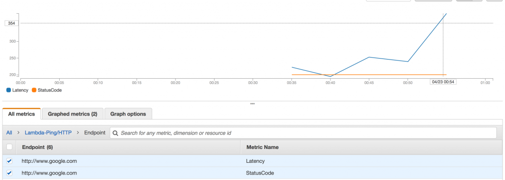
lambda-ping in action

I use this, since it gives me information for more than just my failover internet links (eg my blog, sites, etc) and acts like my Pingdom / Newrelic Synthetics alternative.


Final Result

After setting it all up and testing, I’ve installed the Raspberry Pi into the comms cabinet. I was a bit worried that all the metal casing would create a faraday cage, but it seems to be working OK (I also placed it so that the 3G modem sticks out of the cabinet surrounds).

So far so good, but if I get spotty performance or other issues I might need to consider locating the FailberryPi elsewhere where it can get clear access to the cell towers without disruption (maybe sealed ABS box on the roof?). For my use case, it doesn’t need to be ultra fast (otherwise I’d spend some $ and upgrade to 4G), but it does need to be somewhat consistent and reliable.

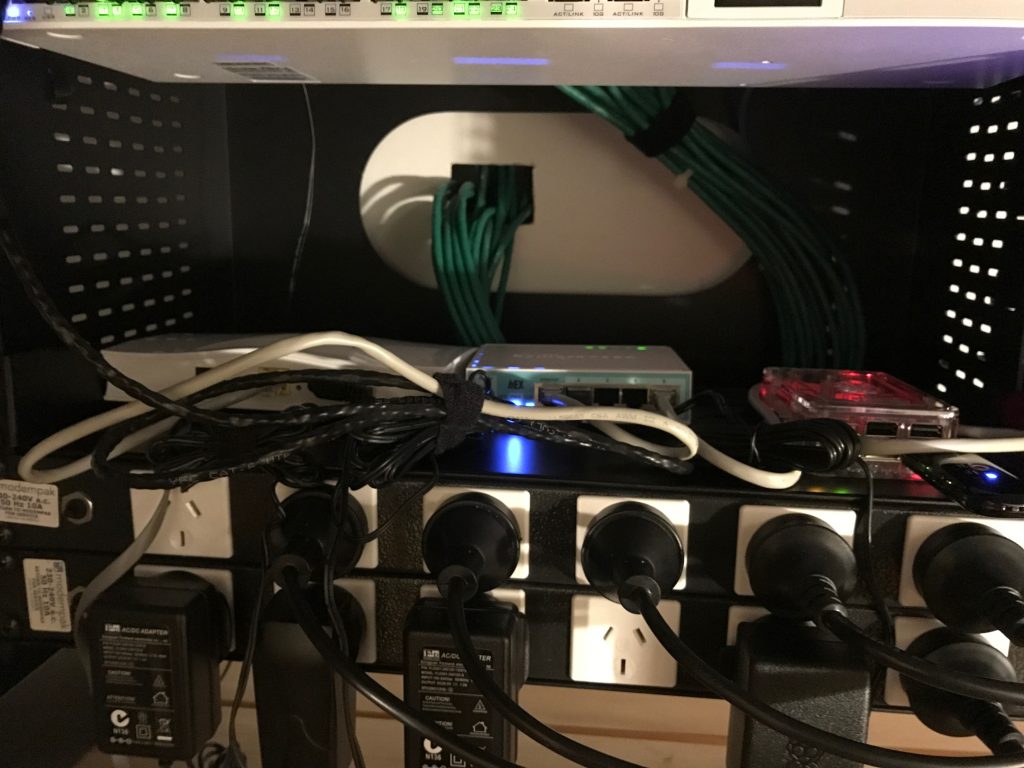
Installed on a shelf in the comms cabinet, along side the main Mikrotik router and the VDSL modem

So far it’s working well – the outbound failover could do with some tweaking to better handle partial failures (eg VDSL link up, but no international transit), but the failover for the inbound works extremely well.

Few remaining considerations/recommendations for anyone considering a setup like this:

  1. If using the one telco for both the wireless and the wired connection, you’re still at risk of a common fault taking out both services since most ISPs will share infrastructure at some level – eg the international gateway. Use a completely different provider for each service.
  2. Using two wired ISPs (eg Fibre with VDSL failover)  is probably a bit pointless, they’re probably both going back to the same exchange or along the some conduit waiting for a  single backhoe to take them both out at once.
  3. It’s kind of pointless if you don’t put this behind a UPS, otherwise you’ll still be offline when the power goes out. Strongly recommend having your entire comms cabinet on UPS so your wifi, routing and failover all continue to work during outages.
  4. If you failover, be careful about data usage. Your computers won’t know they’re on an expensive mobile connection with limited data and they’ll happily download updates, steam games, backups, etc…. One approach is using a firewall to whitelist select systems only for failover (eg IoT devices, alarm, cameras) and leaving other devices like laptops blocked to prevent too much billshock.
  5. Partial ISP outages are still a PITA. Eg, if routing is broken to some NZ ISPs, but international is fine, the failover checks from ap-southeast-2 won’t trigger. Additional ping scripts could help here (eg check various ISP gateways from the Pi), but that’s getting rather complex and tries to solve a problem that’s never completely fixable.
  6. Just buy a Raspberry Pi. Don’t waste time/effort trying to hack some ancient crap together it wastes far too much time and often falls flat. And don’t use an old laptop/desktop, there’s too much to fail on them like fans, HDDs, etc. The Pi is solid embedded electronics.
  7. Remember that your Pi is essentially a server attached to the public internet. Make sure you configure firewalls and automatic patching and any other hardening you deem appropriate for such a system. Lock down SSH to keys only, IP restrict, etc.

Not all routing is equal

Ran into an interesting issue with my Routerboard CRS226-24G-2S+ “Cloud Router Switch” which is basically a smart layer 3 capable switch running Mikrotik’s RouterOS.

Whilst it’s specs mean it’s intended for switching rather than routing, given it has the full Mikrotik RouterOS on it it’s entirely possible to drop out a port from the switching hardware and use it to route traffic, in my case, between the LAN and WAN connections.

Routerboard’s website rate it’s routing capabilities as between 95.9 and 279 Mbits, in my own iperf tests before putting it into action I was able to do around 200Mbits routing. With only 40/10 Mbits WAN performance, this would work fine for my needs until we finally get UFB (fibre-to-the-home) in 2017.

However between this test and putting it into production, it’s ended up with a lot more firewall rules including NAT and when doing some work on the switch, I noticed that the CPU was often hitting the 100% threshold – which is never good for your networking hardware.

I wondered how much impact that maxed out CPU could be having on my WAN connection, so I used the very non-scientific Ookla Speedtest with the CRS doing my routing:

4735498067

After stripping all the routing work from the CRS and moving it to a small Routerboard 750 ethernet router, I’ve gained a few additional Mbits of performance:

4735587010

The CRS and the Routerboard 750 both feature a MIPS 24Kc 400Mhz CPU, so there’s no effective difference between the devices, in fact the switch is arguably faster as it’s a newer generation chip and has twice the memory, yet it performs worse.

The CPU usage that was formerly pegging at 100% on the CRS dropped to around 30% on the 750 when running these tests, so there clearly something going on in the CRS which is giving it a handicap.

The overhead of switching should be minimal in theory since it’s handled by dedicated hardware, however I wonder if there’s something weird like the main CPU having to give up time to handle events/operations for the switching hardware.

So yeah, a bit annoying – it’s still an awesome managed switch, but it would be nice if they dropped the (terrible) “Cloud Router Switch” name and just sell it for what it is – a damn nice layer 3 capable managed switch, but not as a router (unless they give it some more CPU so it can get the job done as well!).

For now the dedicated 750 as the router will keep me covered, although it will cap out at 100Mbits, both in terms of wire speed and routing capabilities so I may need to get a higher specced router come UFB time.

ip6tables: ipv6-icmp vs icmp

I run a fully dual stacked IPv6+IPv4 network on my servers, VPNs and home network – part of this is that I get to discover interesting new first-adopter pains with living in the future (like Networkmanager/Kernel bugs, Munin being stupid, CIFS being failtastic and providers still stuck in the IPv4 only 1980s).

My laptop was experiencing frustrating issues where it was unable to load content from some IPv6 enabled website providers. In my specific case, I was having lots of issues with page loads from WordPress and Gravatar timing out when connecting to them via IPv6, but no issues when using IPv4.

I noticed that I was still able to ping6 the domains in question and telnet to port 80 successfully, which eliminates basic connectivity issues from being the cause. Issues like this where connectivity tests succeed, but actual connections fail, can be a symptom of MTU discovery issues which are a particularly annoying networking glitch to experience.

If you’re behind a WAN link such as ADSL, you’re particularly likely to be affected since ADSL and PPP overheads drop the size of the packets which can be used – in my case, I can only send a maximum of 1460 byte packets, whereas the ethernet default that my laptop will use is 1500 bytes.

In a properly functioning network, your computer will try and send 1500 byte packets to the internet, but the router which has the 1460 byte uplink to your ISP will refuse the packet and advise your computer that this packet is too large and that it needs to break it into smaller ones and try again. This happens transparently and is a standard feature of networking.

In a fucked up improperly functioning network, your computer will try and send the 1500 byte packet to the internet, but no notification advising the correct MTU size is returned or received. In this case your computer keeps trying to re-send the packet until a timeout occurs – from your computer’s perspective, the remote host is unreachable.

This MTU notification is performed by the ICMP protocol, which is more commonly but incorrectly known as being “ping” [whilst ping is one of the functions performed by ICMP, there are many other it’s responsible for, including MTU discovery and connection refused messages].

It’s not uncommon for MTU to be broken – I’ve seen too many system and network administrators block ICMP entirely in their firewalls “for security”, not realising that there’s a lot in ICMP that’s needed for proper operation of a network. What makes the problem particularly bad, is that it’s inconsistent and won’t necessarily impact all users, which leads to those administrators disregarding it as not being an issue with their infrastructure and even blaming the user.

Sometimes the breakage might not even be in a network you or the remote endpoint control – if there’s a router somewhere between you and the website you’re trying to access which has a smaller MTU size and blocks ICMP, you may never receive an MTU notification and you lose the ability to connect to the remote site.

At other times, the issue might be more embarrassing – is your computer itself refusing the helpful MTU notifications being supplied to it by the routers/systems it’s attempting to talk with?

I’m pretty comfortable with iptables and ip6tables, Linux’s IPv4 and IPv6 firewall implementations and use them for locking down servers, laptops as well as conducting all sorts of funky hacks that would horrify even the most bitter drugged up sysadmin.

However even I still make mistakes from time to time – and in my case, I had made a big mistake with the ICMP firewalling configuration that made me the architect of my own misfortune.

On my laptop, my IPv4 firewall looks something like below:

iptables -A INPUT -i lo -j ACCEPT
iptables -A INPUT -m state --state RELATED,ESTABLISHED -j ACCEPT
iptables -A INPUT -p icmp -j ACCEPT
iptables -A INPUT -j REJECT --reject-with icmp-host-prohibited
  • We want to trust anything from ourselves (duh) with -i lo -j ACCEPT.
  • We allow any established/related packets being sent in response to whatever connections have been established by the laptop, such as returned traffic for an HTTP connection – failure to define that will lead to a very unhappy internet experience.
  • We trust all ICMP traffic – if you want to be pedantic you can block select traffic, or limit the rate you receive it to avoid flood attacks, but a flood attack on Ethernet against my laptop isn’t going to be particularly effective for anyone.
  • Finally refuse any unknown incoming traffic and send an ICMP response so the sender knows it’s being refused, rather than just dropped.

My IPv6 firewall looked very similar:

ip6tables -A INPUT -i lo -j ACCEPT
ip6tables -A INPUT -m state --state RELATED,ESTABLISHED -j ACCEPT
ip6tables -A INPUT -p icmp -j ACCEPT
ip6tables -A INPUT -j REJECT --reject-with icmp6-adm-prohibited

It’s effectively exactly the same as the IPv4 one, with some differences to reflect various differences in nature between IPv4 and IPv6, such as ICMP reject options. But there’s one horrible, horrible error with this ruleset…

ip6tables -A INPUT -p icmp -j ACCEPT
ip6tables -A INPUT -p ipv6-icmp -j ACCEPT

Both of these are valid, accepted ip6tables commands. However only -p ipv6-icmp correctly accepts IPv6 ICMP traffic. Whilst ip6tables happily accepts -p icmp, it doesn’t effectively do anything for IPv6 traffic and is in effect a dud statement.

By having this dud statement in my firewall, from the OS perspective my firewall looked more like:

ip6tables -A INPUT -i lo -j ACCEPT
ip6tables -A INPUT -m state --state RELATED,ESTABLISHED -j ACCEPT
ip6tables -A INPUT -j REJECT --reject-with icmp6-adm-prohibited

And all of a sudden there’s a horrible realisation that the firewall will drop ALL inbound ICMP, leaving my laptop unable to receive many important messages such as MTU and rejected connection notifications.

By correcting my ICMP rule to use -p ipv6-icmp, I instantly fixed my MTU issues since my laptop was no-longer ignoring the MTU notifications. :-)

My initial thought was that this would be horrible bug in ip6tables, surely it should raise some warning/error if an administrator tries to use icmp vs ipv6-icmp. The man page states:

 -p, --protocol [!] protocol
    The  protocol of the rule or of the packet to check.  The speci-
    fied protocol can be one of tcp, udp, ipv6-icmp|icmpv6, or  all,
    or  it  can be a numeric value, representing one of these proto-
    cols or a different one.

So why is it accepting -p icmp then? Clearly that’s a mistake, it’s not in the list of accepted protocols…. but further reading of the man page also states that:

A protocol name from /etc/protocols is also allowed.

Hmmmmmmm…..

$ cat /etc/protocols  | grep icmp
icmp       1    ICMP         # internet control message protocol
ipv6-icmp 58    IPv6-ICMP    # ICMP for IPv6

Since /etc/protocols defines both icmp and ipv6-icmp as being known protocols by the Linux OS, ip6tables accepts the protocol argument of icmp without complaint, even though the kernel effectively will never be able to do anything useful with it.

In some respects it’s still a bug, ip6tables shouldn’t be letting users select protocols that it knows are wrong, but at the same time it’s not a bug, since icmp is a valid protocol that the kernel understands, it’s just that it simply will never encounter it on IPv6.

It’s a total newbie mistake on my part, what makes it more embarrassing is that I managed to avoid making this mistake on my server firewall configurations yet ended up doing it on my own laptop. Yet it’s very easy to do, hence this blog post in the hope that someone else doesn’t get caught with this in future.

Munin 2.0.x on EL 5/6 with IPv6

I’ve been looking forwards to Munin 2 for a while – whilst Munin has historically been a great monitoring resource, it’s always been a little bit too fragile for my liking and the 2.x series sounds like it will correct a number of limitations.

Munin 2.0.6 packages recently became available in the EPEL repository, making it easy to add Munin to your RHEL/CentOS/OracleEL 5/6 servers.

Unfortunately the upgrade managed to break value collection for all my hosts, thanks to the fact that I run a dual-stack IPv4/IPv6 network. :-(

Essentially there were two problems encountered:

  1. Firstly, the Munin 2.x master attempts to talk to the nodes via IPv6 by default, as it typical of applications when running in a dual stack environment. However when it isn’t able to establish an IPv6 connection, instead of falling back to IPv4, Munin just fails to connect.
  2. Secondly, the Munin nodes weren’t listing on IPv6 as they should have been – which is the cause of the first problem.

The first problem is an application bug, or possibly a bug in one of the underlying libraries that Munin-node is using. I haven’t gone to the effort of tracing and debugging it at this stage, but if I get some time it would be good to fix properly.

The second is a packaging issue – there are two dependency issues on EL 5 & 6 that need to be resolved before munin-node will support IPv6 properly.

  1. perl-IO-Socket-INET6 must be installed – whilst it may not be a package dependency (at time of writing anyway) it is a functional dependency for IPv6 to work.
  2. perl-Net-Server as provided by EPEL is too old to support listening on IPv6 and needs to be upgraded to version 2.x.

Once the above two issues are corrected, make sure that the munin configuration is correctly configured:

host *
allow ^127\.0\.0\.1$
allow ^192\.168\.1$
allow ^fdd5:\S*$

I configure my Munin nodes to listen to all interfaces (host *) and to allow access from localhost, my IPv4 LAN and my IPv6 LAN. Note that the allow lines are just regex rather than CIDR notation.

If you prefer to allow all connections and control access by some other means (such as ip6tables firewall rules), you can use just the following as your only allow line:

allow ^\S*$

Once done, you can verify that munin-node is listening on an IPv6 interface. :-)

ipv4host$ netstat -na | grep 4949
tcp 0 0 0.0.0.0:4949 0.0.0.0:* LISTEN
ipv6host$  netstat -na | grep 4949
tcp 0 0 :::4949 :::* LISTEN

I’ve created packages that solve these issues for EL 5 & EL 6 which are now available in my repos – essentially an upgraded perl-Net-Server package and an adjusted EPEL Munin package that includes the perl-IO-Socket-Net package as a dependency.

Keeping Android Wifi Awake

I run a number of backgrounded applications on my Android phone, such as Nagios (server monitoring) CSipSimple (VoIP/SIP), OpenVPN (SSL-based VPN) and IMAP idle (push email).

Whilst this does impact battery life somewhat, I’ve got things reasonably well tuned so that the frequency of polling and keepalives is just long enough to prevent firewall timeouts, but long enough to avoid excessive waking of 3G & wifi hardware.

(For example, the default OpenVPN keepalive of 10 seconds is far more aggressive than what is actually needed, in reality, I was able to drop my phone back to one keepalive every 5 minutes – short enough to keep sessions active, but long enough that the transmitting hardware can sleep regularly whilst it isn’t needed).

However one problem I wasn’t able to fix, was the amount that the wifi disconnected – this would really screw up things, since services such as IMAP idle and SIP were trying to run over the VPN, but this would be broken by the VPN being dropped when wifi turned itself off.

I found the fix thanks to a friend who came around and told me about the hidden “Advanced” menu in the wifi network selection page:

When on the wifi network selection screen, you need to press the menu key (not sure what the option is for newer Android phones that don’t have the menu key any more?) and then a single “Advanced” menu item will appear.

Selecting this item will give you a couple extra options, including the important “Keep Wi-Fi on during sleep” option that stops the phone from dropping the wifi connection whenever you turn off the screen.

This resolved my issues with backgrounded services and I found it also made the phone generally perform better when doing any data-related services, since wifi didn’t have to renegotiate with the AP as frequently.

It’s not totally perfect, Android seems to sometimes have an argument with the AP and then drop the connection and waste a minute trying to reconnect, but it’s a lot better than it was. :-)

IPv6 Enabled :-)

A while ago I deployed IPv6 to my flat and have been having fun learning and experimenting with the new addressing methods – at some stage I’m sure I’ll write a few bits up, but there’s mountains of information about IPv6 around already – sometimes the problem is that there is *too* much information.


Thanks to the efforts of my employer and colocation provider, my publicly reachable server now has a /56 IPv6 range which I have just started assigning to various VMs and services. :-D

My first step has been to enable the webserver hosting jethrocarr.com with IPv6 – and as of today, you can now reach this site via IPv4 or IPv6. :-)

[jethro@snagglepuff ~]$ host www.jethrocarr.com
www.jethrocarr.com has address 202.170.163.203
www.jethrocarr.com has IPv6 address 2407:1000:1003:1:216:3eff:fe49:df4e
[jethro@snagglepuff ~]$

If you’re unsure whether you’re reaching via IPv6, try accessing ipv6.jethrocarr.com to check – if it works, you are :-D

[jethro@snagglepuff ~]$ host ipv6.jethrocarr.com
ipv6.jethrocarr.com has IPv6 address 2407:1000:1003:1:216:3eff:fe49:df4e
[jethro@snagglepuff ~]$

Next steps will be to setup mail, XMPP and all other sites and services with dual stack IPv4 and IPv6 for my production servers, I’m sure I’ll post again once complete so that you can all start hammering my services and breaking things. ;-)


Once production is sorted, my following tasks will be replacing the Hurricane Electric tunnel at my flat, with another tunnel to my colocation server, since it means reduced latency for all my IPv6 browsing.

I started off my IPv6 learning with the services provided by Hurricane Electric who provide not only a free IPv4 to IPv6 tunnel service, but also an automated online test platform to check your configuration and test access to your systems.

This has enabled my flat to connect to any IPv6 only resources and the few sites that have IP6 available in production services, but isn’t the greatest since it means all my traffic goes out to the US, adding considerable latency.

(I understand there is now a more local gateway in NZ, provided by SixXS which is also an option, but I figure setting up a 6to4 tunnel at both ends to be an interesting learning curve).