I completed this project a while back and had the images saved up for a blog post – somehow almost a year has gone by since then in a blink of an eye. But anyway, enjoy this delayed update about the exciting world of bathroom fans!
If our house had one deficiency, it would be that the layout of the property has resulted in a rather small and interior only bathroom. Since this bathroom has no direct access to any outside walls for easy ventilation via windows, it instead had a pretty chunky fan already installed when we purchased the property to extract all the shower moisture and other undesirable elements.
By my estimation, the fan would be a good 20 years old and whilst it was doing a good job of extracting air from the bathroom it had two major issues:
- Whilst it extracted air successfully from the bathroom, it didn’t send it anywhere useful – instead it was dumping all the moisture directly into the attic space making the attic (and by extension, the whole house) damp.
- The bathroom roof features a large skylight which is great for making the room feel light and more spacious than it actually is, but it also acts as a giant shower dome, with steam going up into the skylight space and condensing as the fan is not at the highest point of the roof.
The second issue above really started causing significant issues, particularly since the moisture was damaging the paint and plasterboard and with a small bathroom that makes it almost impossible to extend a ladder and reach the super high ceilings, mould was becoming an issue due to inability to access to tackle the moisture.
The situation required remedial work and one day the old fan decided to make the decision easy with the fan cover getting brittle enough that it suddenly fell out of the roof into the bath one evening without warning with a loud crash.
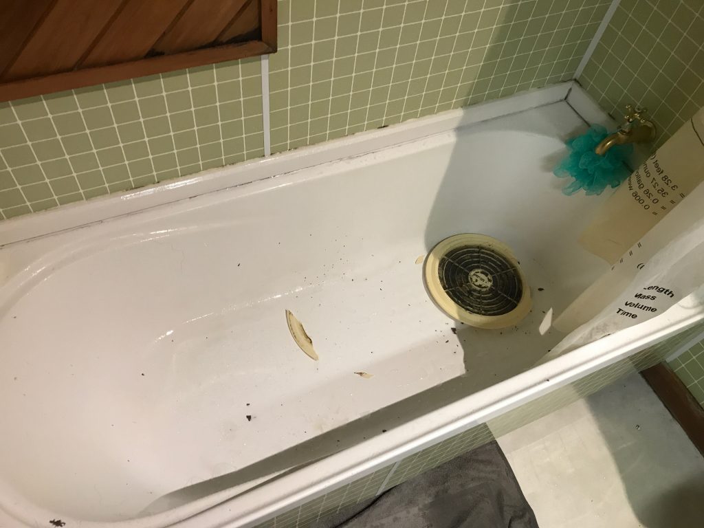
Unscheduled rapid disassembly
For this replacement project, I started with tackling the ventilation problem to make sure the air would actually get extracted out of the house, rather than into the attic (side note: pretty sure venting bathrooms into attics is now forbidden under the building codes for any new installs).
To do this, I brought a 150mm Simx/Manrose Thru Roof Cowl Kit – these can be found at consumer hardware stores and it’s a kit that consists of a plastic tube, the metal cowl ontop and a suitable rubber mounting boot and assorted hardware.
Going through the roof was the only option on this property. Not only is the bathroom in the middle of the house, even if I ran a long ducting run to the nearest walls, there’s no soffits or other tidy location to install the vent without damaging the character of the property.
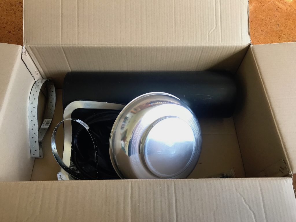
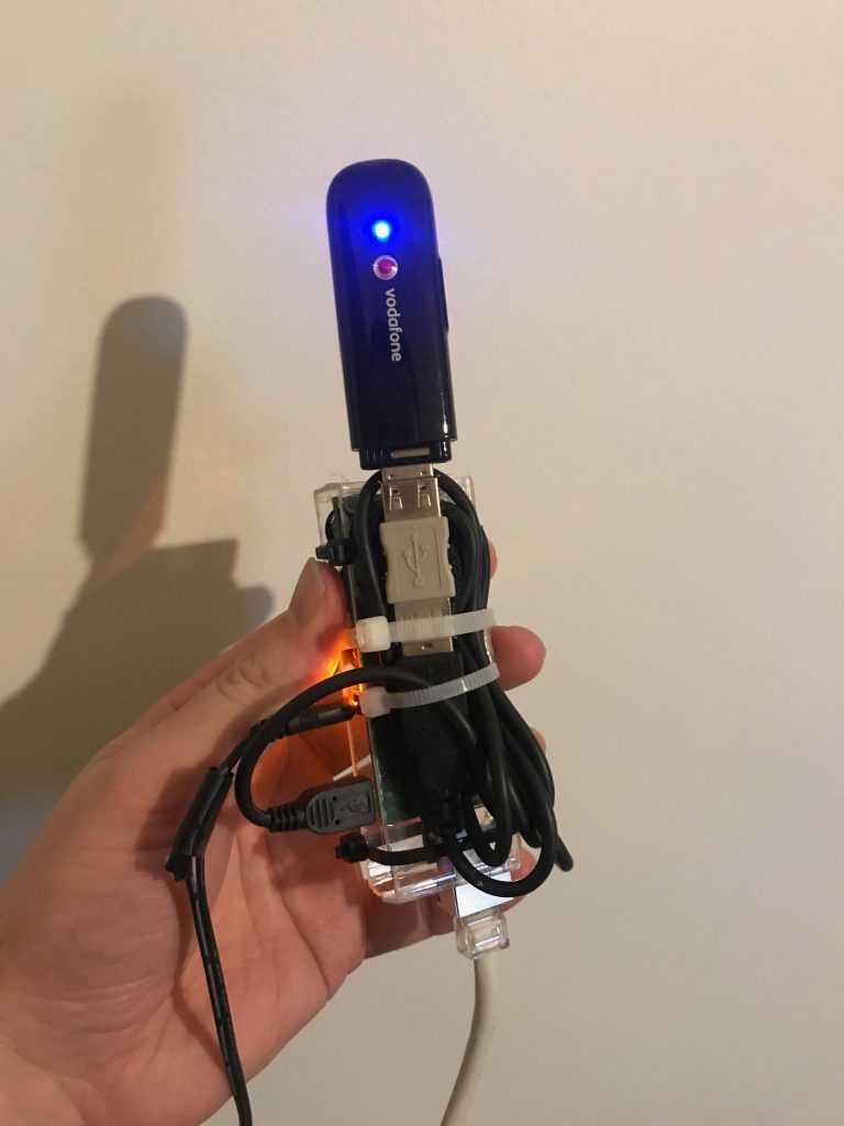
Who cares about the iPhone, *this* is the unboxing you’ve been holding out for.
Installing this was… fun. I purchased my new most-favourite-thing-ever, a reciprocating saw (also called a sabre saw) in order to cut a hole in the roof. This tool has gone on to work hard in a large number of other projects and I consider it an extremely good investment given it’s versatility.

Cut all the things!
One of the quirks of our property being approximately 100 years old is that the roof is sarked with timbers which makes it extremely solid – a proper house, from a more refined age. They stopped building houses like this a long time ago, I think the whole non-sustainable forestry part become a slight issue…
In this situation the solid build both helped and hindered – trying to cut through corrugated iron is a lot easier when there’s not 20mm of native hardwood underneath it as the saw has the habit of picking up the iron and vibrating it like crazy whilst trying to cut the timbers.
But the upside is that it meant I could screw the roof vent directly into the timber and be assured of a tight and long-lasting fit, whereas if I had only floating iron sheets it would have been a lot tricker to get a really tight fit… If this had been the case like in a more modern property, I’d have probably brought some plywood sheets and run them across the rafters to provide a solid surface for screwing the vent into for a similar effect.
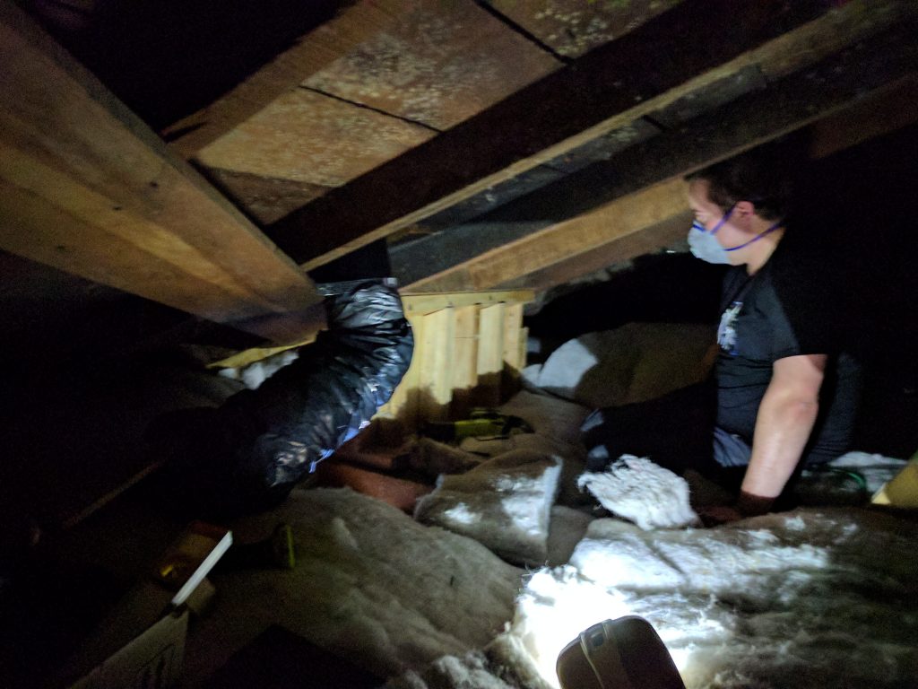
You can get an idea of how solid the house is from this photo inside the attic. In this photo the vent has been installed and ducting attached.
Once I cut the roof hole, I sealed the vent kit rubber boot thoroughly with silicone, with a layer between the boot and the iron sheets, as well as around the edge of the boot and the plastic tube.
The rubber boot has a metal strip allowing it to be bent to fit the corrugated iron snugly. Once the screws went in, it’s a very tight seal and the silicone makes 100% sure it’s sealed.
Note the diagonal placement – this is intentional since it ensures you don’t end up with a pool of water collecting at the top of the boot, which could happen if you placed it square.
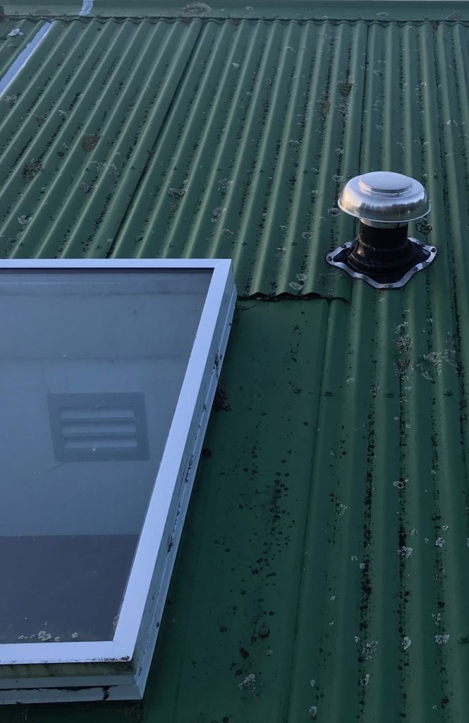
The new vent next to the bathroom skylight. You can see the interior intake through the skylight.
You’ll notice that I’ve cut the hole overlapping two separate sheets. This… isn’t ideal, I’d much rather have cut into a single sheet (easier to seal, less to go wrong as the sheets expand and contract) but I was trying to utilise an existing hole that was already cut in the sarking timbers for what must have been a small vent (maybe an overflow pipe?) in the past to minimise the amount of cutting needed.
This placement also caused another small annoyance for me, which is that the vent is not quite 100% straight and you can notice it sometimes. It’s not an issue for water ingress in the rain, but it annoys me not being 100% perfect. That being said, I’ve had trades install other vents in the property (future project post coming!) and they didn’t get it properly straight either, so I feel somewhat vindicated.
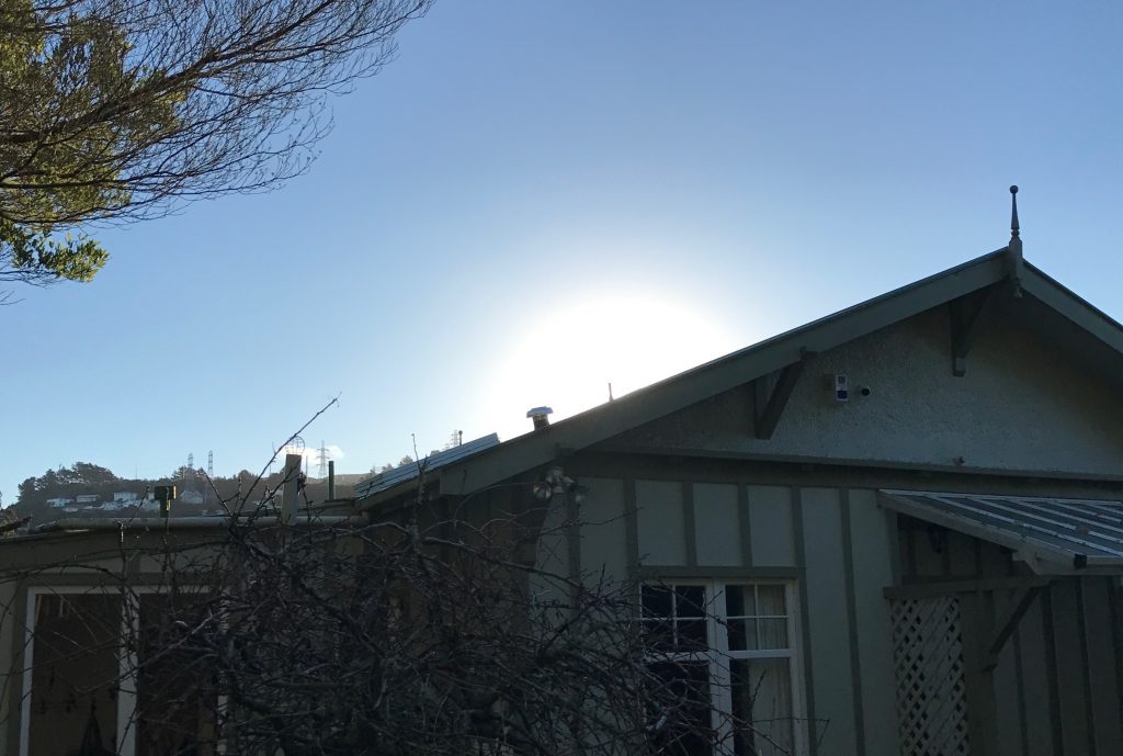
Slightly wonky vent will annoy me everyday forever more…. but if I’ve learnt anything re DIY, don’t fuck with anything that ain’t broke.
To connect the fan to the vent, I brought some insulated ducting. It’s important to use insulated ducting for this, rather than the cheaper uninsulated stuff, since bathroom air is warm and moist – if the ducting is not insulated, you are likely to suffer condensation in the duct as the air cools when it transits through the cooler attic temperatures. By keeping it as warm as possible on it’s way out you can avoid this.
I was worried about some condensation occurring in the vent tube itself – I can’t insulate outside of the roof after all – but this fortunately hasn’t been a problem. Additionally there was some concern that the roof cowl wouldn’t be enough to keep out rain in Wellington winds, but this also hasn’t been an issue – it could be a different situation in more exposed areas of the city and there are cowl fittings that are more suited for unfriendly wind conditions if this was the case.
Next I had to sort out a new fan. I was tempted to keep the existing fan given it’s strong air throughput and the motor still running fine, but I couldn’t easily find a replacement front for it, and the back was completely exposed so there was no easy way to fit the ducting to the back of the fan.
I ended up buying a 250mm “high pressure” fan, but unfortunately this didn’t work out well for me. Despite being described as high pressure, I can confirm that these consumer-available bathroom fans are absolutely useless and not worth buying if you want anything more than a faint breeze.
I had it in place for 1 week, during which time we not only quickly noticed it struggling to remove the steam from the room, but that it was also slowing filling up with water that was condensing in the fan as it struggled the clear the room.
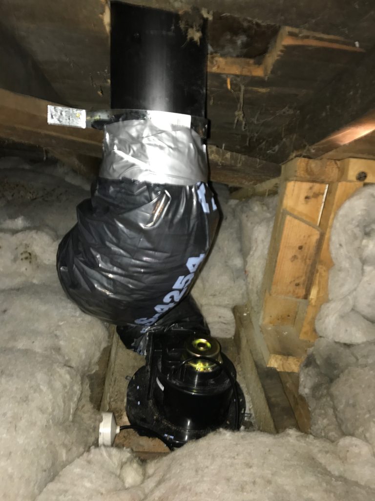
First iteration. Note the side exiting fan which required twisted ducting – not ideal. You can also see the hole in the sarking is larger than needed – that’s because there was a pre-existing hole that I took advantage of which was longer than I needed.
Unfortunately given how much of a complete failure this fan had been, I had to remove it and find an alternative.
The solution was a 150mm pro-series Simix inline fan capable of delivering 166l/s (597m3/hr) air throughput. For comparison, the previous attempted fan was maybe 69l/s (250m3/hr) at best and even that seems dubious given how poorly it performed.
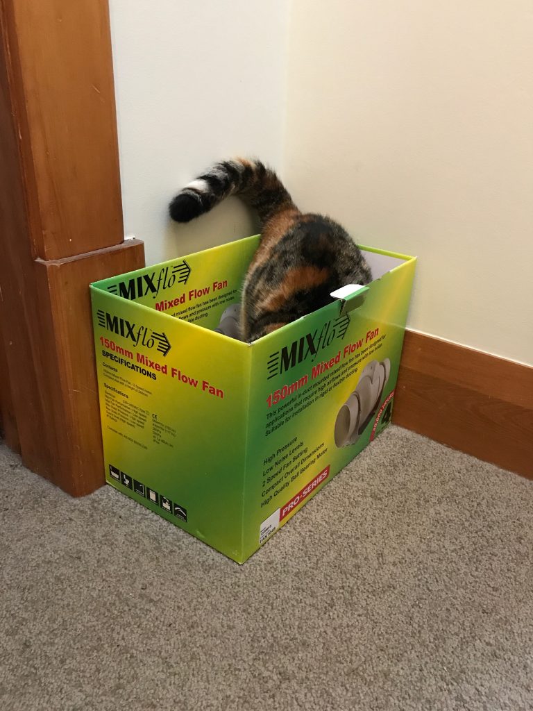
Nimbus is a big fan of this model.
I couldn’t find these at any consumer hardware store and ended up taking advantage of a friend with an electrical trade account who was able to place an order with the supplier for me.
The one key difference with this solution vs my previous attempt is that the fan is inline, which means the bathroom needed a vent installed, with ducting from the intake vent to the fan, then ducting to the outlet vent. This does have some noise advantages since you can place the fan motor further away from the intake.
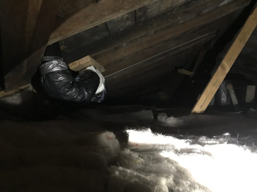
Second iteration. Mounting it on framing timber is a little overkill but I had framing timber and not plywood handy. Because of the solid roof, I found it easier to mount to the underside of the roof, rather than building a platform on the attic floor.
This solution worked much better – the fan is able to extract a considerable amount of air and whilst a bit noisy due to high RPM and small diameter, it does a good job of clearing the bathroom throughout the shower and not letting it build up too much moisture.
When researching this project, it was suggested that you shouldn’t be clever and mix duct sizes (eg a 200mm fan into a 150mm vent), so I kept the same spec throughout – if I had gone for a larger roof vent and duct in the beginning, I might have gone with something larger to get more throughput but also larger fans tend to be quieter (as a general rule).
The other big positive of this approach is that I was able to solve the skylight condensing problem by putting the new intake vent directly into the side of the skylight wall to rapidly extract out the air.
This is working extremely well – whilst we have the existing damage from past moisture build up which will require remedial work (complete repaint, maybe some new plastering), since putting in this new vent we’ve had very little moisture build up since the fan keeps the air moving in the skylight preventing condensation. And since heat rises, all the steam from the shower naturally gravitates towards the vent anyway.
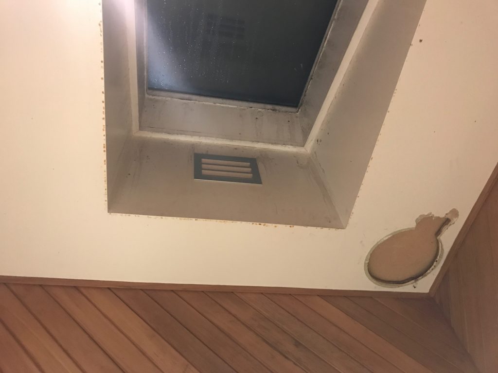
This photo illustrates the issue with the placement of the old vs new fan – the old one did nothing for all the stream that wafted up into the skylight space, vs the new one keeping that space clear.
I found it really hard to find an intake vent that wasn’t horribly ugly and plasticky, so ended up paying a bit of a premium for an aluminium model. It ended up being a right pain to install so maybe I should have gone for a cheap nasty plastic 150mm that would have been simple to fit, but I think it was worth it and looks good (once I fix all the paintwork anyway). I even managed to get it dead centre which given I was cutting it out from inside the attic due to inability to get ladder high enough in the bathroom was a pretty good outcome.
Anyway despite the challenges, I’m pretty happy with this setup now. It’s working reliably, I’ve checked the ducting a few times to make sure there’s been no moisture build up or water ingress from outside (both good!) so I’m expecting this solution to last for a long time.
I still need to fix the plasterboard and paint job in the bathroom. It’s kind of stuck pending access to a more flexible ladder/indoor scaffold type system just due to the height of the bathroom roof and very limited placement points for ladders. Still it annoys me daily so it’ll get fixed sooner or later when I get really sick of it looking so bad.
Rough cost for the project was around $500-600 NZD in parts – the most expensive bits being the fan motor, and then the roof vent kit – a wall vent solution would be a fair bit cheaper.
If I was doing this project again from scratch, I’d probably have done a few things differently.
- I’d almost certainly have considered getting the bigger model and going for a 200mm fan able to shift 272l/s (980m3/hr) of air. The current model is good, but I’d almost have enjoyed the bathroom being like a vacuum cleaner for maximum dryness. And the larger fan size should be a bit quieter.
- I utilised the existing hardwired appliance circuit as a straight replacement of one fan for another, but it would have been good to get a timer fan installed, to keep it running for a given time period following the fan being switched off. This is something I might end up getting an electrician to install for me in future anyway, but I might have been able to save some money getting a model of fan with the timer circuit build in, vs having to now buy a timer module for the circuit.
- I don’t love the ducting install. I ended up with two 90 degree bends which were unavoidable due to the original hole being intended for a fan directly below the hole, but I’d have preferred an almost straight run to ensure minimal workload for the fan (maybe some noise reduction too?). This could have been easily accomplished by installing the fan further up the roof line and running the duct straight from the interior vent, through the fan, then up and out the roof. But it wasn’t worth sealing one hole and cutting another to fix.
- If I ever build a house, I’m making sure the bathrooms have at least one exterior wall to make ventilation so much simpler!
- I put in all the vent bolts (hex head) using an automotive socket set by hand. This works totally fine but just takes ages, so an impact driver would have been a nice addition to the tool kit. That being said, I’ve since done other hex head screws using a socket adaptor drill bit which allows me to use the cordless drill to drive hex head screws, although admittedly lacking the high torque of a proper impact driver.